You got that right! I thought maybe it was just me, but WTF! This last time I pulled the rubber piece off the bike and mated it with the plastic first before installing, but then I was dealing with trying to figure out where to cram that all in around the shifter, side stand, etc. I do miss naked bikes sometimes...who ever designed this plastic, rubber interlocking tab arrangement is a sadistic SOB.

-
WOULD YOU LIKE TO BE ABLE TO POST? REGISTER FOR COG MEMBERSHIP
All registration must be done through the club's main webpage: To register / join COG, click here
For instructions to convert to full membership, click here
-
Can't post after logging to the forum for the first time... Try Again - If you can't post in the forum, sign out of both the membership site and the forum and log in again. Make sure your COG membership is active and your browser allow cookies. If you still can't post, contact the COG IT guy at IT@Concours.org.
You are using an out of date browser. It may not display this or other websites correctly.
You should upgrade or use an alternative browser.
You should upgrade or use an alternative browser.
What have your done to your C14 today
- Thread starter COGnosticator
- Start date
Mine do the same, wear a full helmet and you won't hear a thing!! Seriously though, I do ride short trips with no helmet just to hear anything and everything going on below. The brake rub seems minimal after releasing the front brakes.Installed Ohlins rear shock, then went for a short 30-40 mile test run to play with some settings.
It was the KA109 for 2010 and up(not the 2008-2009 recommended KA709) but it bolted right up on my 2009.
I had to fab an L shaped bracket to mount the remote pre-load adjuster, but otherwise uneventful.
Does anyone know the definitive difference between the KA109 and the KA709?
Once back, I rebuilt the front brake master cylinder, and installed Galfer stainless lines up front.
It started to rain right as I finished up, I took it out for a short 20 miles or so anyway.
The front brakes are driving me crazy.
When I get on the front brakes hard, I can hear the pads against the rotors for several seconds after I release the brake lever.
Then they go silent until I hit the front brake again.
There is no pulsing, or apparent dragging(unless it is doing it for those few seconds after I release the lever).
I had previously pulled the front calipers, cleaned the pistons, checked/lubed rotor buttons and installed new EBC HH pads.
I did not install new seals for the pistons, maybe they are swollen? I noticed the noise with the stock pads too, so I don't believe it is related to the pads.
Is this brake noise normal for the Concours 14? Suggestions besides earplugs?
The most puzzling sound I hear is the howling whistles on I guess the intake? or injectors? I'm not sure where it comes from, almost like a turbine sound.
Put on Murph’s ball bearing shifter shaft… dadgum smooth as silk! Put on a little winglet on top of the windshield as well, I’m still trying to decide how much I like that but the shifter if awesome!!I have seen this thread on other bike forums like the BMW GS and FJR and these threads always cost me moneyby seeing what other people have done to their bike. I didn't see one for the C14 so I thought I would start it. ;D
Today I installed the G2 throttle tamer to my 2013, fairly straight forward and easy job, then I put the throttlemeister on (thanks Reid) took a little adjustment to make it work right, but now I am ready to go, well after I get a new LED headlight for the one I mucked up
So, what have you done to your C14 today. :great:
I use a Healtech Quickshifter, I may look into this for even silkier feel.Put on Murph’s ball bearing shifter shaft… dadgum smooth as silk! Put on a little winglet on top of the windshield as well, I’m still trying to decide how much I like that but the shifter if awesome!!
It made a big difference on mine. Think it depends on how wore your shifter is. The bushing was toast on mine.I use a Healtech Quickshifter, I may look into this for even silkier feel.
I actually didn't see much difference, my bushing was ok. 
I spent a couple of hours after work today nursing a beer while gathering and test fitting gear for my upcoming trip - heading to the Bun Cooler, plus two extra nights of camping in Montana and Idaho, should be ~1700 miles. Last night met up with my riding friend and shared a few lessons learned about moto camping and planned a rough route for this trip with him. Now I am getting excited and counting the hours until departure time on the morning of Friday the 20th... This will be my first multi-day trip on the C14 and my first ride more than 300 miles since I picked it up last October.
I'm fairly certain I will be able to fit everything I need in the panniers, top case, and tank bag without needing to strap a drybag/duffel on the bike. This includes 'coffee service' in the morning, tools, and extra fluids for both myself and the bike. I'm quite impressed with the cargo capacity!
I'm fairly certain I will be able to fit everything I need in the panniers, top case, and tank bag without needing to strap a drybag/duffel on the bike. This includes 'coffee service' in the morning, tools, and extra fluids for both myself and the bike. I'm quite impressed with the cargo capacity!
Take a quick test ride, make certain you’re happy with everything - weight / placement before venturing off where you may be unwilling to stop. The C14 is large enough to not be bothered by a bit of weight imbalance, still a good idea to double-check before committing.I spent a couple of hours after work today nursing a beer while gathering and test fitting gear for my upcoming trip - heading to the Bun Cooler, plus two extra nights of camping in Montana and Idaho, should be ~1700 miles. Last night met up with my riding friend and shared a few lessons learned about moto camping and planned a rough route for this trip with him. Now I am getting excited and counting the hours until departure time on the morning of Friday the 20th... This will be my first multi-day trip on the C14 and my first ride more than 300 miles since I picked it up last October.
I'm fairly certain I will be able to fit everything I need in the panniers, top case, and tank bag without needing to strap a drybag/duffel on the bike. This includes 'coffee service' in the morning, tools, and extra fluids for both myself and the bike. I'm quite impressed with the cargo capacity!
Also remember your suspension setting will be off now, you will need to reset sag at a minimum. Not everyone does this but the weight does make a difference in ride performance.
Wayne, Carol & Blue
I was working on the 2009 C14 that is new to me and discovered an issue with the left side pannier mechanism. Half of the plastic pivots under the case opening handle are broken and come right off. The case opens and closes OK, but I am concerned that stress on the good pivots will result in them breaking too. I see no parts for the panniers on Partzilla. Ebay has a complete pannier for $400, which is pretty costly for poaching the mechanism. Any ideas?
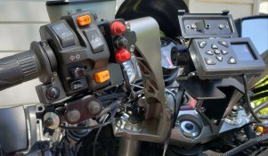
Installed the switch brackets I'd designed and built for the new master cylinder clamps (Gem Police Sales) after building wiring harnesses for each section. These will control HF/6M and 2M/440 ham radio transceivers. PTT for both radios, up/down tuning, band and VFO/Memory selection for the VHF/UHF dual-bander along with a tuning "lock" button for the HF/6M rig are present in this cluster.
Much more wiring and assembly to do but it's getting closer.
Much more wiring and assembly to do but it's getting closer.
Attachments
New rear tire. New oil and filter
Installed the switch brackets I'd designed and built for the new master cylinder clamps (Gem Police Sales) after building wiring harnesses for each section. These will control HF/6M and 2M/440 ham radio transceivers. PTT for both radios, up/down tuning, band and VFO/Memory selection for the VHF/UHF dual-bander along with a tuning "lock" button for the HF/6M rig are present in this cluster.
Much more wiring and assembly to do but it's getting closer.
Impressive switch-work, clean and professional looking.
Question: Looking in the background, does your hand go over?.... or under?..... to get to the stoveknob switch?
Please post here with photos when it's finished. I'm not a radio guy, but I like to glean ideas from others that seem to install stuff well.
Marty, it goes over.
That mount (drilled on the back side for a RAM Ball) is available from Beaudry Police Authority Sales. You have to use riser blocks with it. I'd advise having PhillipInTexas make bars that are 1" longer than OEM if wanting to mount radio controls.
I also bought the replacement master cylinder clamps (including one which mounts a head/taillight cutoff switch, which I'm going to re-purpose) from Beaudry. Steve offers a switch bracket for the left-hand clamp which mounts two switches. I designed one on CAD which accommodates three; likewise for the right-hand clamp/light switch assembly (two push buttons there). The CAD files can be made available to others wanting to reproduce this work, and I designed a number of them to accommodate various industry-standard waterproof switches.
Definitely going to take lots of pics of this as it comes closer to completion. The radio box and auxiliary battery setup going on the back of the bike proved to be a huge engineering challenge with regards to wiring, routing of accessory harnesses and design of circuits to protect the charging system - but I think I've managed to sort all the boondoggles which ultimately killed Kawasaki's corporate "C14P" program.
@Bagger John - Very nice setup! And thanks for the breakdown of parts and install so far. Can't wait to read/see the final setup. Wow I didn't go that far for my ham radio setup. I'm using a Sena SR10 to connect with my Icom ID4100a on the handlebar with a speaker/mic box devised by another ham guy from the link below. The SR10 has a wired PTT button on the left grip which connects to my Sena 50S in my helmet.

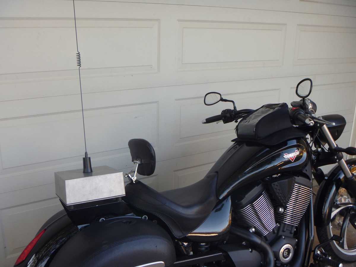
Since the face is detachable/removable and placed on the front bars, the main box lives on the back of the bike with a regular PL259 mount using a Comet SBB5 antenna on the DIY case. Pretty much similar to what this is setup looks like but on a C14 and different radio/antenna. When I'm off the bike and need to communicate, I turn the switch on the DIY speaker/mic box.
 marc-hq.org
Since the face is detachable/removable and placed on the front bars, the main box lives on the back of the bike with a regular PL259 mount using a Comet SBB5 antenna on the DIY case. Pretty much similar to what this is setup looks like but on a C14 and different radio/antenna. When I'm off the bike and need to communicate, I turn the switch on the DIY speaker/mic box.
Install: Icom IC-2730 on a Victory Vegas
I have a 2m/440 mobile radio on my Victory Vegas. I enjoy using it for public service at athletic events and chatting with my riding companions.
Robert - I also have Sena gear here and am going to build an interface for the Motochello MC-200 which will let me use a Freewire, SR-10 or SM-10 with it. The '12 I'm converting will be a solo bike so I can use the passenger headset connection to connect the Bluetooth unit.
I currently have Yaesu FTM-10SRs on several of my bikes. Here's the control head of an FTM-10R (high power version) that's replacing one of the -10SRs on this one. Also shown is the lighting switch unit I mentioned earlier, and in this pic you can see the control head for my IC-703+.
Much dressing and securing of the cabling remains, and I have to crimp connectors (TE Mini Mate-N-Lok) on the ends of the wires I just ran from the switches. Always some detail or another to tend to.
Went to a locksmith after trying to get help from local hardware stores to make an emergency key for the emergency FOB to use during an emergency if the main FOB is lost/broke/forgotten. He used an old Yamaha key blank that works perfect. Emergency FOB and key under seat and emergency key to use for emergencies on key ring attached to my riding pants.
'10-up, I presume?Emergency FOB and key under seat and emergency key to use for emergencies on key ring attached to my riding pants.
If an actual FOB, leave the battery out until needed.
How am I going to borrow his bike then?'10-up, I presume?
If an actual FOB, leave the battery out until needed.

I have a spare battery. (hint/hint)How am I going to borrow his bike then?
Ride safe, Ted
it's the emergency flat FOB for my '22, slipped it into a recessed slot under the seat and duct taped it in. Again, I'm using 4 times the number of keys on a huge key ring than when I had my C-10. Stupidest, dumbest, most idiotic, short sighted, profoundly moronic idea ever envisioned to place on a vehicle much less a motorcycle.
Oh yeah 2022 model, you must have missed the story. Here it is if you have time to kill---> https://forum.concours.org/index.php?threads/c-14-availability-update.54401/'10-up, I presume?
If an actual FOB, leave the battery out until needed.
By the way, just fyi: Emergency FOBs (the little Domino sized passive items that came with Gen IIs) should be able to be programmed for the Gen I '08-'09s as well. They are much cheaper than an active FOB and still a handy bit of extra anti-stranded insurance item to have available even if you have two active Fobs for your Gen I C14 (leave one active at home for emergency overnight delivery if needed).
I disagree, but no matter, you are not alone in your opinion as several here and elsewhere have the same sentiments.Stupidest, dumbest, most idiotic, short sighted, profoundly moronic idea ever envisioned to place on a vehicle much less a motorcycle.
How so? I have a Fob deep in my pants pocket and 2 keys on a lanyard in my outer gear pocket, one for the Top Case and one for all the stuff on the bike. You?Again, I'm using 4 times the number of keys on a huge key ring than when I had my C-10.
In addition to an emergency fob key and an emergency key to get to the emergency fob, I have 2 separate keys for the 2 separate helmet locks because Kawasaki did not put helmet locks on the bike, up to 4 extra keys now I have to carry, I only carried ONE key on the C-10 with a spare duct taped to the frame under a side cover, so, ONE key I carried at all times to work every lock and ignition. I wonder if I went to a Kawasaki dealer how much that blank key, if I was even allowed to buy one, would have cost? Sorry, that's stupid in my book any way you look at it.
This is a handy bit of info. I have a KDS3 and cables for my '12 - need to buy a set for my '08. The '12 has one active and one passive FOB; the '08, 2 active. I want to add an active to the '12 and a passive to the '08.By the way, just fyi: Emergency FOBs (the little Domino sized passive items that came with Gen IIs) should be able to be programmed for the Gen I '08-'09s as well. They are much cheaper than an active FOB and still a handy bit of extra anti-stranded insurance item to have available even if you have two active Fobs for your Gen I C14 (leave one active at home for emergency overnight delivery if needed).
I have to take pics of mine, but there are aftermarket helmet locks which use either A or B pattern keys. My '08 has the A while the '12 has the B. I found several of each and re-keyed them to match the FOB keys, appropriately....Kawasaki did not put helmet locks on the bike...
OK, understood.In addition to an emergency fob key and an emergency key to get to the emergency fob, I have 2 separate keys for the 2 separate helmet locks because Kawasaki did not put helmet locks on the bike, up to 4 extra keys now I have to carry, I only carried ONE key on the C-10 with a spare duct taped to the frame under a side cover, so, ONE key I carried at all times to work every lock and ignition. I wonder if I went to a Kawasaki dealer how much that blank key, if I was even allowed to buy one, would have cost? Sorry, that's stupid in my book any way you look at it.
I never cared for helmet locks, so their absence never bothered me. Once you've seen a helmet hanging on the back of bike being used as a urinal, spitoon, or a garbage can by a ne'er-do-well passer-by, the idea just loses it's appeal. (I've seen all three {after the fact}, still holding out for sighting usage as a vomit bag.)
However, I'll leave you alone now, we all do something different and see things differently, some hate that, but others (me) enjoy the variety.
The likelihood of this occurring is directly proportional to the type of event one attends, and the places one parks. A couple summer runs I frequent have a wide assortment of bikes and bikers, and if the group catches someone screwing with someone else's property...let's just say I wouldn't want to be on the receiving end of what followed.Once you've seen a helmet hanging on the back of bike being used as a urinal, spitoon, or a garbage can by a ne'er-do-well passer-by, the idea just loses it's appeal. (I've seen all three {after the fact}, still holding out for sighting usage as a vomit bag.)
The One Simple Trick of avoiding 1%-focused events goes a long way in minimizing shenanigans, too.
Hmmm...so KDS Cables are different for Gen I and Gen II?This is a handy bit of info. I have a KDS3 and cables for my '12 - need to buy a set for my '08. The '12 has one active and one passive FOB; the '08, 2 active. I want to add an active to the '12 and a passive to the '08.
I will point out that in my post I said "should", that was based on the assumption that since the active FOBs of Gen Is have passive chips in them that Mama Kaw continued the same system with the Gen IIs. However if the hook up cables are different perhaps there are other differences that go against my assumptions.
Could it be that Gen Is don't have six slots for each type of Fob like the Gen IIs do? Seems unlikely, but possible. Once you get the Gen I cables, try programming your Gen II passive fob to the Gen I bike before you outlay the cash for another passive fob, just to be sure. Let us know how it goes, please.
Last edited:
Yeah, I don't go there, all incidents were outside restaurants in daylight. Sometimes it just takes one squid or a 1% wann-a-be to get someone mad at all motorcyclists. My helmet is either locked in a case or on the chair next to me.The likelihood of this occurring is directly proportional to the type of event one attends, and the places one parks. A couple summer runs I frequent have a wide assortment of bikes and bikers, and if the group catches someone screwing with someone else's property...let's just say I wouldn't want to be on the receiving end of what followed.
The One Simple Trick of avoiding 1%-focused events goes a long way in minimizing shenanigans, too.
I tried to figure a way to reuse the old helmet locks from the C-10, keyed the same, unless I fabricated a bracket, no, it would only do away with one key anyway. The ones I have on the C-14 are from AST. Whenever I lock a helmet, I try to turn it so it's sideways and I always close the visor.
In 40 years of riding, I've never heard of the the things you described pertaining to hanging helmets, that's not to say you have not seen them, that's pretty hardcore stuff, and, that in all the places and events I've been to if that were to ever happen, I'm quite sure the coroner may be needed afterwards.
In 40 years of riding, I've never heard of the the things you described pertaining to hanging helmets, that's not to say you have not seen them, that's pretty hardcore stuff, and, that in all the places and events I've been to if that were to ever happen, I'm quite sure the coroner may be needed afterwards.
Your wish is my command. I did one for the locks I mentioned which goes on the rear fender. There's a company which offers a dual-lock version, but theirs is steel and rather heavy - I'd advise against using this setup unless a brace is used. Gem Police may offer a brace, as I know they're standard equipment on their C14P conversions. My old lock plate is available if you want it.I tried to figure a way to reuse the old helmet locks from the C-10, keyed the same, unless I fabricated a bracket, no, it would only do away with one key anyway. The ones I have on the C-14 are from AST. Whenever I lock a helmet, I try to turn it so it's sideways and I always close the visor.
The lock/license plate mount I designed can be fabricated from aluminum or steel and incorporates mounts for a pair of Whelen 0S - series marker lights in addition to the lock. I can provide .dxf files if you want one of the online laser-cutting services to fabricate it for you. The one I use - SendCutSend - will also do powdercoating.
Where I've gone and usually go, the occasional 1%er and "citizen" alike will jump on a bike vandal with aplomb. We're all there to have a good time with motorcycles.In 40 years of riding, I've never heard of the the things you described pertaining to hanging helmets, that's not to say you have not seen them, that's pretty hardcore stuff, and, that in all the places and events I've been to if that were to ever happen, I'm quite sure the coroner may be needed afterwards.
Here's the plate bracket I mentioned, mocked up on the rear fender and including the brace.. I have M6 security screws for all the fastener locations, including the two which bolt the plate carrier to the fender.

Got the fairings back on the bike yesterday just ahead of severe T-storms that moved through the area. The top dash panels and tank cover are next; a little finishing up of cabling and a custom rubber rain cover for the Fuze Block then I can install those pieces plus the windshield.
Back of the bike saw test-fitting of the Corbin rider saddle and trying to figure out how to make the rear brake reservoir play nicely with everything. Another thread in the forum asks for help in identifying a bracket - I found one attached to a reservoir and bought the whole thing.
It's getting there.
My '08's final drive decided to start leaking so I snagged a replacement (along with parts to fix the first one) and plan on getting to that soon.
Over the last week or so I've been putting bodywork back on the '12. And removing it as parts come in and I want to redo something or another.
A few bits of electrickery: First, the new radio box replaces the rear seat - and as such, the seat lock is no longer required. The mechanism and cable actually get transplanted into the box to secure the lid. This leaves a hole in the side cover. What to do?
Install a Powerlet port. I used a couple of nylon washers on front and back of the panel, and a waterproof boot covers the plug on the back.
Next was an interface ("Y") cable that brings lines from both turn signals, running and brake lights into the top box - where they'll connect to the Whelen LIN3 lights at the rear of the box. Auxiliary run/stop lights and turn signals are nice when you're dealing with blind cagers. (Side note: At one time I had a couple of Gold Wings, each with Drag Specialties and Custom Dressers saddlebag light bars. People would still act oblivious to my presence even with the entire rear end lit up - go figure.)
I'd mentioned earlier about designing an interface for the Yaesu FTM-10R that's to be mounted in the radio box. That consists of a long multi-conductor cable (I used two Yaesu CTM-11s) and a couple of small boxes to hold the electronics. One is mounted under the tank cover and contains the electronics required to make the handlebar-mounted buttons control the radio. The other is mounted around the space where the now-unneeded OEM tool box was fastened.
A peek inside reveals some 1:1 600 ohm isolation transformers. They're inserted in the Left/Right Output and Mic Input lines. The IC-703+ HF rig I'm going to install along with the VHF/UHF radio may also require these in the audio I/O lines - but we'll see how it works without them.

You can do an Iron Butt already! I completed one on my skinny Ninja 1000 last year. The seat was not my friend! I vowed to not do another Iron Butt until I had a more comfortable motorcycle. Hence, last week I got my '21 Concours! I may just have to do another before the end of summer. My point is: your motorcycle is more than capable. You'll have a great time!!View attachment 30955Added my new tank bag. Kawasaki OEM. Very nice quality fit and finish. A little pricey but I'm very happy with the investment. It's bigger than I thought it would be, especially when unzipped and fully expanded. This gets me one step closer to being ready to make an Iron Butt attempt.
Not specifically today, but in the last few days: Murphs risers plus AST 1" pullbacks, Murph's lowering pegs. Bought a Corbin modular from another member, also ordered a Sargent Low seat. Phil's rack, plus Kawasaki Top Case. Did 180 miles today, stock seat was killing me last 50 miles.
Today, I finally got around to rechecking the wiring for my Rostra. It is installed on my 2011 Canadian model ZG1400. Everything works fine except.....When I turn on the signal lights, the CC disengages. I looked through all the help I could find on this sight and the problem is...there is NO black connector under the front left faring cover. Mine is white. Also, none of the wire colours suggested work for the clutch disengage. The grey wire is a constant disengage signal. So...I will resign myself to no clutch disengagement which leaves me with a properly working system in 5th and 6th at speeds of 50MPH (80KPH) and above. Below that or in lower gears, the throttle response is too abrupt causing repeated surging. In the zone it works in is where I need CC for 90% of the time so am reasonably happy. Although it would be nice to have the clutch disengage working.
I got the top box mounting plate on, put the top box on and began wiring things up.
I'm using a solid state flasher unit as there are now LEDs in all the turn signals. I made wye adapters for the turn signals and brake/taillight; the harness for these runs into the top box and interfaces with four Whelen LIN3 lights (1ea red and amber on the left and right rear sides). These were programmed for steady burn; the turn signal elements parallel the rear OEM units while the red lights are wired in series then connected to a Badlands ILL-01. They're lower intensity running lights when configured this way, and the Badlands unit's sense wire is connected to the OEM brake light lead. Hit the brakes and the two basically triple in intensity.
All this is run through a customer Powerpole distribution box. Pics of the ongoing setup when I get things tie-wrapped. It looks...unslightly at the moment.
Looking forward to the pictures and overall setup! Wondering what moto-service you do besides ham radio (ARES?)?I got the top box mounting plate on, put the top box on and began wiring things up.
I'm using a solid state flasher unit as there are now LEDs in all the turn signals. I made wye adapters for the turn signals and brake/taillight; the harness for these runs into the top box and interfaces with four Whelen LIN3 lights (1ea red and amber on the left and right rear sides). These were programmed for steady burn; the turn signal elements parallel the rear OEM units while the red lights are wired in series then connected to a Badlands ILL-01. They're lower intensity running lights when configured this way, and the Badlands unit's sense wire is connected to the OEM brake light lead. Hit the brakes and the two basically triple in intensity.
All this is run through a customer Powerpole distribution box. Pics of the ongoing setup when I get things tie-wrapped. It looks...unslightly at the moment.
I'm looking to add some lights and horn from Feniex but always open to what others are using.
2nd day of our recent 11 Day 5,600 mile trip was 917 miles (got detoured from 887 plan). 1,000 - no biggie.You can do an Iron Butt already! I completed one on my skinny Ninja 1000 last year. The seat was not my friend! I vowed to not do another Iron Butt until I had a more comfortable motorcycle. Hence, last week I got my '21 Concours! I may just have to do another before the end of summer. My point is: your motorcycle is more than capable. You'll have a great time!!
Wayne, Carol & Blue
Lookin' good! But all this work and only seeing views of pieces is making me crazy. When will we see the finished bikes?
Ride safe, Ted
Ride safe, Ted
I have four bikes at the moment (two C14s; two Valkyries). The Valks have OEM CBs. My Tourer has an FTM-10SR installed, while the Interstate has a Kennedy FRSet-4 that allows me to connect a ham radio "talky", an FRS/GMRS or MURS transceiver. My '08 C14 has a JMCB-2003 and a special FRSet-4 which allows selectable operation of its installed FTM-10SR or an FRS/GMRS/MURS HT.Looking forward to the pictures and overall setup! Wondering what moto-service you do besides ham radio (ARES?)?
I'm looking to add some lights and horn from Feniex but always open to what others are using.
The '12 can run its two ham radios in the top box, or I can remove the HF/6M unit's chassis and install a BCD-996XT trunking scanner in its place. An RH-96 controller goes on the bar mount (in place of the ham transceiver's control head) and I can then do GPS-based scanning of our statewide 800MHz MARCS-II system while underway.
All this stuff is extremely handy in avoiding traffic jams, wrecks, anything to spoil the ride.
I suppose it is possible that the Canadian models had different wiring colors...but it seems unlikely?Today, I finally got around to rechecking the wiring for my Rostra. It is installed on my 2011 Canadian model ZG1400. Everything works fine except.....When I turn on the signal lights, the CC disengages. I looked through all the help I could find on this sight and the problem is...there is NO black connector under the front left faring cover. Mine is white. Also, none of the wire colours suggested work for the clutch disengage. The grey wire is a constant disengage signal. So...I will resign myself to no clutch disengagement which leaves me with a properly working system in 5th and 6th at speeds of 50MPH (80KPH) and above. Below that or in lower gears, the throttle response is too abrupt causing repeated surging. In the zone it works in is where I need CC for 90% of the time so am reasonably happy. Although it would be nice to have the clutch disengage working.
I think you may be using Brian's (B.D.F.) instruction's from his GEN I model. On my 2010 I found the white connector under the left front boot and it was a tight fit, and difficult to work with, so I connected on the opposite side of of the white connector on the Red w/Green stripe. See if you can find that wire and if the rest of the wires look like the ones in the photo below. If so, let's see if we can get the clutch disconnect working first then maybe we can move on and figure out the turn signal thing.

ALSO: I don't know what you've seen and haven't seen there are several different sources of info. I've found the diagram below to be very useful. I think it was made by Fred Harmon, I'm not sure if he updated a Brian drawing or did it from scratch himself...regardless as to who gets the credit, both gentlemen have been helpful with my C14 modifications over the years. You'll note in the diagram the green NSS wire goes to a black wire where on the other side of the (white) connector it becomes Red w/green stripe which is where I attached my Rostra's green NSS wire. When testing the Rostra using the trouble shooting mode I think it is important that the bike is on it's center stand with the side stand in the UP position (IIRC)
.
Last edited:
Just means you need more practice!You got that right! I thought maybe it was just me, but WTF! This last time I pulled the rubber piece off the bike and mated it with the plastic first before installing, but then I was dealing with trying to figure out where to cram that all in around the shifter, side stand, etc. I do miss naked bikes sometimes...
Wayne
Thanks a bunch. I have used the Diagram (end here) and tried both the WHITE side and the RED AND GREEN side (with soldered connections). The result is turn signal operation cancels the CC. LOL. Thanks for confirming that the white connector is the correct one. I am having so much fun with this. The next owner will likely think(what are all these deadens connections for?) The trouble shooting mode is OK and the rest works as advertised. Thanks again for the info supplied. I will surely get it at some point.I suppose it is possible that the Canadian models had different wiring colors...but it seems unlikely?
I think you may be using Brian's (B.D.F.) instruction's from his GEN I model. On my 2010 I found the white connector under the left front boot and it was a tight fit, and difficult to work with, so I connected on the opposite side of of the white connector on the Red w/Green stripe. See if you can find that wire and if the rest of the wires look like the ones in the photo below. If so, let's see if we can get the clutch disconnect working first then maybe we can move on and figure out the turn signal thing.
ALSO: I don't know what you've seen and haven't seen there are several different sources of info. I've found the diagram below to be very useful. I think it was made by Fred Harmon, I'm not sure if he updated a Brian drawing or did it from scratch himself...regardless as to who gets the credit, both gentlemen have been helpful with my C14 modifications over the years. You'll note in the diagram the green NSS wire goes to a black wire where on the other side of the (white) connector it becomes Red w/green stripe which is where I attached my Rostra's green NSS wire. When testing the Rostra using the trouble shooting mode I think it is important that the bike is on it's center stand with the side stand in the UP position (IIRC)

Ted,Lookin' good! But all this work and only seeing views of pieces is making me crazy. When will we see the finished bikes?
Ride safe, Ted
I'm at the point where I can wire the top box side lights then put the lid back on it, wash the bike and go ride it some place nice for pics. Before I do that I'd like to mount the radio chassis in the radio tray, fasten a piece of DIN rail (which will be used to secure the transceiver interface boxes) then check the new battery tray I have coming in. Seems an Odyssey PC-680 is too tall for this application - so I'm going to use a PC-545 and that requires a new tray. Need to double-check the battery layout before fastening the DIN rail.
When I take pics of the setup, the old adage "20lbs of stuff in a 10lb box" will immediately come to mind. This exercise has been....challenging. Some of the choppers and custom cruisers/baggers I've built over the years haven't been as convoluted.
Sounds like my garage. There is a term for that.... Blivet...although defined poundage varies, the principle is the same.the old adage "20lbs of stuff in a 10lb box" will immediately come to mind.
Looking forward to the photos.

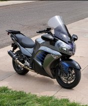
2016. Carbon wrapped mirrors, front fender, and tank cover. Carbon Delkevic exhaust, Shoodaben "Mountain" ECU, Michelin Road 6 GT's, gradient tinted Vstream touring screen, cruise control, frame sliders, super bike foam grips, custom paint touches here n there.
Attachments
If you look closely at the wiring diagram I referenced and the photo I supplied it appears you may have tapped into the wrong Red w/green stripe Wire? maybe? ??? (just brain stormin' here)Thanks a bunch. I have used the Diagram (end here) and tried both the WHITE side and the RED AND GREEN side (with soldered connections). The result is turn signal operation cancels the CC. LOL. Thanks for confirming that the white connector is the correct one. I am having so much fun with this. The next owner will likely think(what are all these deadens connections for?) The trouble shooting mode is OK and the rest works as advertised. Thanks again for the info supplied. I will surely get it at some point.
Where the one black wire coming from the clutch lever switch goes to (through the connector) the proper Red w/Green stripe wire...there is also a red w/green stripe wire going to the turn signal circuit on the opposite side of the connector at a different pin location. Try comparing my photo and the wire location of your red w/green stripe, does your red w/green stripe wire go through the connector to an orange wire or a Black wire?
Orange would be the turn signal circuit.
Note: the wiring diagram shows proper connections for wire connections through the connector....but is not accurate for pin out locations nor adjacent wire color locations, only accurate for across (through) connector connections. <--this can lead to inaccurate troubleshooting conclusions and connections.
Last edited:
Hmm. A Great suggestion. I will look again with this new insight.If you look closely at the wiring diagram I referenced and the photo I supplied it appears you may have taped into the wrong Red w/green stripe Wire? maybe? ??? (just brain stormin' here)
Where the one black wire coming from the clutch lever switch goes to (through the connector) the proper Red w/Green stripe wire...there is also a red w/green stripe wire going to the turn signal circuit on the opposite side of the connector at a different pin location. Try comparing my photo and the wire location of your red w/green stripe, does your red w/green stripe wire go through the connector to an orange wire or a Black wire?
Orange would be the turn signal circuit.
Note: the wiring diagram shows proper connections for wire connections through the connector....but is not accurate for pin out locations nor adjacent wire color locations, only accurate for across (through) connector connections. <--this can lead to inaccurate troubleshooting conclusions and connections.
Really sharp looking bike! Great work.2016. Carbon wrapped mirrors, front fender, and tank cover. Carbon Delkevic exhaust, Shoodaben "Mountain" ECU, Michelin Road 6 GT's, gradient tinted Vstream touring screen, cruise control, frame sliders, super bike foam grips, custom paint touches here n there.
I happened to be rummaging around in a parts bin today and found a set of GL1800 front footpads. These had been modified for a previously owned 2001 C10. Remembering how much I liked that mod (I had forgotten that I had removed them prior to sale) I checked the fit on my 2011 C14. Fit right on. (already attached to a fitment mod) I really like this mod and it is well worth the slight adjustment to rear brake and shifter use.
Can you post a pic? And no risk of scraping?I happened to be rummaging around in a parts bin today and found a set of GL1800 front footpads. These had been modified for a previously owned 2001 C10. Remembering how much I liked that mod (I had forgotten that I had removed them prior to sale) I checked the fit on my 2011 C14. Fit right on. (already attached to a fitment mod) I really like this mod and it is well worth the slight adjustment to rear brake and shifter use.
What about rear foot pads, fit there?
Wayne
Finally! Thanks a bunch for the tips. The other end was not red and green BUT there was only one black on the opposite side and that was all it needed. CC system working at 100% now.I suppose it is possible that the Canadian models had different wiring colors...but it seems unlikely?
I think you may be using Brian's (B.D.F.) instruction's from his GEN I model. On my 2010 I found the white connector under the left front boot and it was a tight fit, and difficult to work with, so I connected on the opposite side of of the white connector on the Red w/Green stripe. See if you can find that wire and if the rest of the wires look like the ones in the photo below. If so, let's see if we can get the clutch disconnect working first then maybe we can move on and figure out the turn signal thing.
ALSO: I don't know what you've seen and haven't seen there are several different sources of info. I've found the diagram below to be very useful. I think it was made by Fred Harmon, I'm not sure if he updated a Brian drawing or did it from scratch himself...regardless as to who gets the credit, both gentlemen have been helpful with my C14 modifications over the years. You'll note in the diagram the green NSS wire goes to a black wire where on the other side of the (white) connector it becomes Red w/green stripe which is where I attached my Rostra's green NSS wire. When testing the Rostra using the trouble shooting mode I think it is important that the bike is on it's center stand with the side stand in the UP position (IIRC)
Many hands make light work.
The L/S down shows the fitment of the foot peg. The L/S folder shows that it can fold (spring loaded) all the way back if needed. Will they touch down earlier than stock? Yes. They are out about an inch wider and about an inch lower at the top but not much lower at the bottom.Can you post a pic? And no risk of scraping?
What about rear foot pads, fit there?
Wayne
Attachments
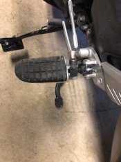
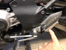
I have a plan for an improved version of the adaptor. These were set up for the C10. I think a bit of redesign will allow better shifting comfort and not as much offset to the outside.The L/S down shows the fitment of the foot peg. The L/S folder shows that it can fold (spring loaded) all the way back if needed. Will they touch down earlier than stock? Yes. They are out about an inch wider and about an inch lower at the top but not much lower at the bottom.
2012 C14 60K miles maintenance sweep
1) Flushed out the radiator three times with distilled water and replaced the Honda branded coolant with new,
2) Replaced the rear differential gear lube,
3) Replaced front and rear wheel bearings with new Nachi's along with the seals of course,
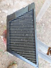
4) Air filter change,
5) Mounted the new Road 6GTs front and rear along with valve stem seals,
6) Replaced the TPMS batteries with fresh ones, (I get a low battery warning on the front when temps drop below 55 degrees),
7) Cleaned and lubed the wheel to final drive splines with Honda Moly Paste,
8) Put the orbital polisher to the C Bailey screen to get minor scratches and dings out of my view,
9) Replaced the black windshield covers because they had cracked from repeated mounting and remounting,
10)Replaced the shift lever rubber and both rider peg rubbers as they were showing their age.
Now ready for the ride out to Lolo Pass!
Safe Travels!
Gilbysan aka - Fat Ninja
1) Flushed out the radiator three times with distilled water and replaced the Honda branded coolant with new,
2) Replaced the rear differential gear lube,
3) Replaced front and rear wheel bearings with new Nachi's along with the seals of course,
4) Air filter change,
5) Mounted the new Road 6GTs front and rear along with valve stem seals,
6) Replaced the TPMS batteries with fresh ones, (I get a low battery warning on the front when temps drop below 55 degrees),
7) Cleaned and lubed the wheel to final drive splines with Honda Moly Paste,
8) Put the orbital polisher to the C Bailey screen to get minor scratches and dings out of my view,
9) Replaced the black windshield covers because they had cracked from repeated mounting and remounting,
10)Replaced the shift lever rubber and both rider peg rubbers as they were showing their age.
Now ready for the ride out to Lolo Pass!
Safe Travels!
Gilbysan aka - Fat Ninja
Nice! I have a Cee Bailey screen as well and have interest about the process of polishing out scratches. Please let me know.2012 C14 60K miles maintenance sweep
1) Flushed out the radiator three times with distilled water and replaced the Honda branded coolant with new,
2) Replaced the rear differential gear lube,
3) Replaced front and rear wheel bearings with new Nachi's along with the seals of course,
4) Air filter change,
5) Mounted the new Road 6GTs front and rear along with valve stem seals,
6) Replaced the TPMS batteries with fresh ones, (I get a low battery warning on the front when temps drop below 55 degrees),
7) Cleaned and lubed the wheel to final drive splines with Honda Moly Paste,
8) Put the orbital polisher to the C Bailey screen to get minor scratches and dings out of my view,
9) Replaced the black windshield covers because they had cracked from repeated mounting and remounting,
10)Replaced the shift lever rubber and both rider peg rubbers as they were showing their age.
Now ready for the ride out to Lolo Pass!
Safe Travels!
Gilbysan aka - Fat Ninja
There is a You Tube video on polishing a motorcycle windshield using Mothers aluminum polish. I used that method on a Clearview shield on my Valkyrie with good results.
I will check it out. Good to hear that it worked out for you. My screen is mostly good with only a couple areas that could use a polish.There is a You Tube video on polishing a motorcycle windshield using Mothers aluminum polish. I used that method on a Clearview shield on my Valkyrie with good results.
8) Put the orbital polisher to the C Bailey screen to get minor scratches and dings out of my view,
There is a You Tube video on polishing a motorcycle windshield using Mothers aluminum polish. I used that method on a Clearview shield on my Valkyrie with good results.
Well to each their own, I just painted mine black on the backside. I also occasionally chip off some of the bugs, but since they just come back I don't do that as much as I used to.
I saw an interesting alternative at this year's COG National, sort of best of both worlds...maybe.


Didn't do much on the '12 Enforcer conversion today but Friday was spent building most of the remaining wiring harnesses for power for the ham rigs, audio and PTT connections for the HF/6M rig. Also mocked up the Givi S150 rack on the second top box lid, then located the mounting holes for a pair of MLS-200 waterproof speakers. Got this idea from Channing, a Kawi rep I met at one of the ROK rallies. His '08 sported a pair of Kawi accessory speakers from their personal watercraft line and I liked the concept. The Yaesu speakers are a bit heavier than the Kawi units, so I needed a more substantial place to fasten them instead of on the upper fairing covers. The top box provided a neat solution.
Installed some SAENG rubber stripping/wind deflecting stripping around factory shield to get a bigger envelope of quieter air over my helmet. This is the newest design as I had some on my 2001 C-10, it does ok, it's not a bigger windshield but it works as advertised and gives me a few more inches of quiet air over factory shield.

Gen 4 Edging Noise Turbulence Reduction Available
Ride making too much noise? Saeng Gen 4 edging reduces motorcycle wind noise and turbulence an important aid in preventing hearing loss. Contact us for Gen 4 edging... the noise turbulence reduction tool.
saeng.com
Redesign of footage adapters is complete. Visually , they look the same but actually lower the pegs by means of moving them 1/2 inch back (on the angled mounts). More toe room and noticeably better comfort .I have a plan for an improved version of the adaptor. These were set up for the C10. I think a bit of redesign will allow better shifting comfort and not as much offset to the outside.
How’s the wind coverage?Installed a Copperdawg Windscreen on my 2011Atomic Silver and went for a ride. I live in Houston and it works for me. By the way, they were great to deal with.
I realize you are in TX and HOT, regardless - hot / cold a 600, 700, 800, 900+ mile day with poor wind protection is not comfortable, especially 2-up…
Same goes for being in a crouched position for that many miles - blah.
Curious to hear your experience,
Wayne. Carol & Blue
Hey Rob, I wish Bailey still made screens. Of all I have tried, it has worked the best for me.Nice! I have a Cee Bailey screen as well and have interest about the process of polishing out scratches. Please let me know.
First, I clean the screen of stuck on bugs and stuff using Brillianize acrylic cleaner and a Microfiber Towel. I use a cheap harbor freight orbital polisher and their terry cloth pads. Starting with Novus #2 acrylic polish (it is brown in color) I place some on the pad and dab it on the part of the screen I am doing. After giving it a bit of work, not pressing hard just letting the buffer do its thing, I use a high quality microfiber towel to wipe away the residue then repeat the process for another section of the screen. Usually, I take on 1/3 of the screen at a time. Once I am done with the Novus #2, I move on to the Brillianize, a new clean pad on the polisher, wet the pad with Brillianize and spray the screen, again polish for a bit. Then wipe away the excess with a clean M-F towel and I'm done.
Note1: I also do the inside of the screen and recommend that IF you do the inside, do it first, then the out facing side after that. That way you don't risk depositing new scratches on the outward facing side of the screen.
Note2: I do this with the screen off so that I do not stress the lifting assembly when working the top of the screen.
Note3: This process also works great for the headlight lens that tends to get pitted over time.
Brillianize-
Novus #2-
That is very interesting.Well to each their own, I just painted mine black on the backside. I also occasionally chip off some of the bugs, but since they just come back I don't do that as much as I used to.
I saw an interesting alternative at this year's COG National, sort of best of both worlds...maybe.

Thanks for the detailed instructions. I love the Cee Bailey screen and want to keep it fresh for years to come. Will likely do the polishing when she goes into winter storage. Too much great riding to do now. I love this Concours!Hey Rob, I wish Bailey still made screens. Of all I have tried, it has worked the best for me.
First, I clean the screen of stuck on bugs and stuff using Brillianize acrylic cleaner and a Microfiber Towel. I use a cheap harbor freight orbital polisher and their terry cloth pads. Starting with Novus #2 acrylic polish (it is brown in color) I place some on the pad and dab it on the part of the screen I am doing. After giving it a bit of work, not pressing hard just letting the buffer do its thing, I use a high quality microfiber towel to wipe away the residue then repeat the process for another section of the screen. Usually, I take on 1/3 of the screen at a time. Once I am done with the Novus #2, I move on to the Brillianize, a new clean pad on the polisher, wet the pad with Brillianize and spray the screen, again polish for a bit. Then wipe away the excess with a clean M-F towel and I'm done.
Note1: I also do the inside of the screen and recommend that IF you do the inside, do it first, then the out facing side after that. That way you don't risk depositing new scratches on the outward facing side of the screen.
Note2: I do this with the screen off so that I do not stress the lifting assembly when working the top of the screen.
Note3: This process also works great for the headlight lens that tends to get pitted over time.
Brillianize-
Novus #2-
I was out for 130 miles with 2 stops between 7 and 10 AM. A LOT of wind against my upper body at any speed but I am used to this after having a Multistrada for a few years. My Shoei RF 1400 was great in the wind at highway speeds. I think 600 plus days would be roughing it. I only do day trips or morning trips during the really hot weather. I'll put my V Stream back on when it gets cold.How’s the wind coverage?
I realize you are in TX and HOT, regardless - hot / cold a 600, 700, 800, 900+ mile day with poor wind protection is not comfortable, especially 2-up…
Same goes for being in a crouched position for that many miles - blah.
Curious to hear your experience,
Wayne. Carol & Blue
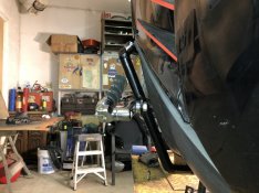
I wanted a bracket to bolt up my old passenger backrest off my C-10 onto the C-14, nobody online made one and those that had a backrest attached were over $200. I went down to a local metal fabricator and had a bracket made up for $40 that will bolt to my Phil's luggage rack. I will pick it up next week.
I wanted a bracket to bolt up my old passenger backrest off my C-10 onto the C-14, nobody online made one and those that had a backrest attached were over $200. I went down to a local metal fabricator and had a bracket made up for $40 that will bolt to my Phil's luggage rack. I will pick it up next week.
Definitely looking forward to pictures.
I'm getting it today, I'll try with pic, I got this new fangled flippy cell phone thingy that takes photos, It think you hook it to the lap top with a wire and you can transfer photos? New territory for me. Stand by, probably tomorrow.
It's just a piece of 3/16 sheet aluminum, 9"X5" with holes cut to correspond to the slots in Phil's rear rack, with a 1" tab bent at 80 degrees to compensate for the angle of the rack and holes to bolt on my old back rest that I think was an old California sport Touring item? I'll painting it this weekend.


It's just a piece of 3/16 sheet aluminum, 9"X5" with holes cut to correspond to the slots in Phil's rear rack, with a 1" tab bent at 80 degrees to compensate for the angle of the rack and holes to bolt on my old back rest that I think was an old California sport Touring item? I'll painting it this weekend.
Last edited:
Good luck with that!I'm getting it today, I'll try with pic, I got this new fangled flippy cell phone thingy that takes photos, It think you hook it to the lap top with a wire and you can transfer photos? New territory for me. Stand by, probably tomorrow.

Finished the wiring harness for the MLS-200 speakers. The remaining task is to connect the cables from the MC-200 to an RJ-45 interface that provides remote control for the bike's HF/6M rig - allowing all the new buttons on the handlebars to function. I can then install the radio tray and everything is operational without the secondary battery.
About that: Several posts back I mentioned having to go with a sealed 12V/9AH unit. In monkeying around with the radio tray mounting brackets, I figured a way to secure the battery and the smart isolator (a BT-100) to the top box cross piece - so the entire assembly can be dropped in after wiring it up. One of the top boxes I'd gotten off the auction side had extra holes drilled in its cross piece - possibly for this very purpose, though I haven't been able to pin down the exact type and model of battery bracket which was used in the LE conversion.
I have a collection of multiband (HF/VHF/UHF) antennas in the stash. One of the remaining tasks is to configure one that's both high speed/low drag AND actually works well on 10/6/2M and 440 MHz simultaneously. They're either big and unwieldy or small and inefficient.
No one said engineering was easy, though it can be elegant - most times by accident.
Ok I work up early and it’s cool out so I changed my oil installed new spark plugs. Slipped a new air filter in. Had a FI light code 26. So checked the intake cam senser, the wire was broken so soldered it . The 2017 runs nice and smooth again! Have fun go rideI have seen this thread on other bike forums like the BMW GS and FJR and these threads always cost me money
Today I installed the G2 throttle tamer to my 2013, fairly straight forward and easy job, then I put the throttlemeister on (thanks Reid) took a little adjustment to make it work right, but now I am ready to go, well after I get a new LED headlight for the one I mucked up
So, what have you done to your C14 today. :great:
I have an old corbin and I removed cover and trimmed a piece of memory foam and now it’s comfy on long rides.Installed a lightly used Corbin seat (thanks jumbo_sf), one of Phil's outstanding luggage racks, a Givi V47NNT topcase, and TechSpec tank grips. :motonoises:
Oh and my handle bars arrived and installed those and a zero gravity window. Now need to get plates and ride ride ride!!I have an old corbin and I removed cover and trimmed a piece of memory foam and now it’s comfy on long rides.
Yesterday I swapped the final drive on the '08 to a non-leaking (hopefully...) eBay unit. Today I have to tighten up the Glenda fork lights then go test-ride it. The '12 needs its secondary battery isolator mounted, the rest of the power distribution wiring installed and the radio tray/radio chassis installed - then it's good to go.
Installed a set of the dual Motohorns mentioned a few posts ago, easy, simple, true plug-n-play, free shipping, $70 total to your door, choice of chrome or black color, includes all wiring needed, installation took about 1 hour once I figured out the wiring sequence required and fiddled with tucking them up under the fairing using the factory horn mounting holes. THEY ARE LOUD! High/low tone, 130DB. If you act now and PM me, I will tell you the secret code for a 20% discount on your next Motohorn order, you will not however, receive, 6 free Ginsu knives.
I have no dog in this race, this is just a nice product that worked for me and a card was included in the box telling me to tell everyone I know about this discount offer.
I have no dog in this race, this is just a nice product that worked for me and a card was included in the box telling me to tell everyone I know about this discount offer.
PM INBOUNDInstalled a set of the dual Motohorns mentioned a few posts ago, easy, simple, true plug-n-play, free shipping, $70 total to your door, choice of chrome or black color, includes all wiring needed, installation took about 1 hour once I figured out the wiring sequence required and fiddled with tucking them up under the fairing using the factory horn mounting holes. THEY ARE LOUD! High/low tone, 130DB. If you act now and PM me, I will tell you the secret code for a 20% discount on your next Motohorn order, you will not however, receive, 6 free Ginsu knives.
I have no dog in this race, this is just a nice product that worked for me and a card was included in the box telling me to tell everyone I know about this discount offer.
Installed a set of the dual Motohorns mentioned a few posts ago, easy, simple, true plug-n-play, free shipping, $70 total to your door, choice of chrome or black color, includes all wiring needed, installation took about 1 hour once I figured out the wiring sequence required and fiddled with tucking them up under the fairing using the factory horn mounting holes. THEY ARE LOUD! High/low tone, 130DB. If you act now and PM me, I will tell you the secret code for a 20% discount on your next Motohorn order, you will not however, receive, 6 free Ginsu knives.
I have no dog in this race, this is just a nice product that worked for me and a card was included in the box telling me to tell everyone I know about this discount offer.
Aw maaaannn, no Ginsu knife set? Bummer. LOL
But seriously, how heavy is the kit? Are we adding back the 20lbs we saved by removing the OEM exhaust?
Thx for sharing with us BTW. Cheers, AB
Not much use for the knives…. But I could enjoy a K-Tel album!Installed a set of the dual Motohorns mentioned a few posts ago, easy, simple, true plug-n-play, free shipping, $70 total to your door, choice of chrome or black color, includes all wiring needed, installation took about 1 hour once I figured out the wiring sequence required and fiddled with tucking them up under the fairing using the factory horn mounting holes. THEY ARE LOUD! High/low tone, 130DB. If you act now and PM me, I will tell you the secret code for a 20% discount on your next Motohorn order, you will not however, receive, 6 free Ginsu knives.
I have no dog in this race, this is just a nice product that worked for me and a card was included in the box telling me to tell everyone I know about this discount offer.
Y'all are having waaaay too much fun.
Laker recently machined new Turnbuckle adapters for my C-14.
He and I are tinkering with a different design.
These are smaller than I had previously and his (Professional) machining is far better than I did as a Hobby Machinist.
While doing so, I discovered that I had damaged my Area P Mufflers with my previous design.
(I rode the bike with the adapters in place and wore off a little of the Carbon Fiber Material from the Area P Mufflers).
err Duhhhh..
They're not broken thru. I just want to do a patch to prevent a possible problem.
My plan is to put some epoxy in the worn area. (I have {Grey} JB weld)
Does anyone happen to know where I can get some Black Epoxy (preferrably high temp)?
Ride safe, Ted
Look at Grainger.Y'all are having waaaay too much fun.
Laker recently machined new Turnbuckle adapters for my C-14.
He and I are tinkering with a different design.
These are smaller than I had previously and his (Professional) machining is far better than I did as a Hobby Machinist.
While doing so, I discovered that I had damaged my Area P Mufflers with my previous design.
(I rode the bike with the adapters in place and wore off a little of the Carbon Fiber Material from the Area P Mufflers).
err Duhhhh..
They're not broken thru. I just want to do a patch to prevent a possible problem.
My plan is to put some epoxy in the worn area. (I have {Grey} JB weld)
Does anyone happen to know where I can get some Black Epoxy (preferrably high temp)?
Ride safe, Ted
There are a few more wiring items to finish up on the C14P conversion (I'm waiting on parts again) but last night I decided to take the "bike" out and test the mechanicals - including the valve clearance job I started late last August.
An FYI: As part of the LE package, Kawasaki offered an electronic speed limiter that restricts the bike to 135MPH. One came up on eBay; someone (not me) bought it.
Mine is unencumbered by such nonsense. It's wearing a set of rear crash guards, the top box and a number of handlebar-mounted radio comms items; atridiculous/ludicrous REDACTED MPH the handling is still neutral and steady.
I have two radio trays for the top box. The one which was installed for the test has no radio equipment mounted, and there's enough space for a towel, my gloves and a few other necessities.
The Corbin seat is nice. Definitely feels better than the stock saddle or Kawi's optional Touring saddle (which isn't a bad seat in and of itself).
An FYI: As part of the LE package, Kawasaki offered an electronic speed limiter that restricts the bike to 135MPH. One came up on eBay; someone (not me) bought it.
Mine is unencumbered by such nonsense. It's wearing a set of rear crash guards, the top box and a number of handlebar-mounted radio comms items; at
I have two radio trays for the top box. The one which was installed for the test has no radio equipment mounted, and there's enough space for a towel, my gloves and a few other necessities.
The Corbin seat is nice. Definitely feels better than the stock saddle or Kawi's optional Touring saddle (which isn't a bad seat in and of itself).
Thanx.Look at Grainger.
I tried Grainger. Trying to find something in their *&%^ catalog frustrated me.
Partly because I'm a computer illiterate.
Ted,
If you can't source it anywhere else, try McMaster-Carr: https://www.mcmaster.com/epoxy-resins/
Also cross referencing the JB Weld P/N I found this from your favorite retailer:
https://www.walmart.com/ip/J-B-Weld...e-and-Gap-Filler-Syringe-Black-25mL/168950018
https://www.amazon.com/J-B-Weld-50139-Plastic-Adhesive/dp/B01IBOK7FE
https://www.tractorsupply.com/tsc/product/j-b-weld-plastic-bonder-black-50139
Thanx all. I looked at the Black Epoxy you found, and all that I saw were low temp epoxy.
As it will be on the (hot) mufflers, I opted to buy "High temp" {grey} Epoxy.

My original thought was to add the epoxy and wanted the black epoxy so it wouldn't show up.
But, I decided that color wasn't a concern. (Can paint the epoxy if needed)
I may I think I may pop rivet a *wear plate over the area. (to prevent a possible re-accurance)
If I do so, the wear plate will be approx. (2.0 x 3.0 / 0.030" thick Aluminum or Stainless)
Ride safe, Ted
As it will be on the (hot) mufflers, I opted to buy "High temp" {grey} Epoxy.
Epoxy-Steel Reinforced, High Strength-2 Pack, Dark Grey for Multi Surfaces 43425990464 | eBay
Find many great new & used options and get the best deals for Epoxy-Steel Reinforced, High Strength-2 Pack, Dark Grey for Multi Surfaces at the best online prices at eBay! Free shipping for many products!
www.ebay.com
My original thought was to add the epoxy and wanted the black epoxy so it wouldn't show up.
But, I decided that color wasn't a concern. (Can paint the epoxy if needed)
I may I think I may pop rivet a *wear plate over the area. (to prevent a possible re-accurance)
If I do so, the wear plate will be approx. (2.0 x 3.0 / 0.030" thick Aluminum or Stainless)
Ride safe, Ted
Installed the AST riser adaptors.
With the 2" bar risers, it was nice with the stock seat. When I installed the Corbin seat, it raised me up almost 2" which almost nullified the 2" risers, back to square one. I ordered the AST adaptors which brought the bars back about a 1" and raise them yet again another 1/2", all with no modifications to the wiring or brake lines. Now, the ergos remind me of the C-10 with the Russell Day Long Seat.
I ordered those adaptors last Thursday afternoon, they were shipped the following day, Friday, they arrived at my house Monday and they were on the bike by 2PM, now that's service folks, plus, they are well made and worth the money and came with everything you need to install them which took about 20 minutes.
Took her for a ride in the cooler weather (80s)

I saw this set up at the national at eureka springs this year. Have a couple more pics of it. Dont know whose bike it was but im thinking if doing something similar for myself..I wanted a bracket to bolt up my old passenger backrest off my C-10 onto the C-14, nobody online made one and those that had a backrest attached were over $200. I went down to a local metal fabricator and had a bracket made up for $40 that will bolt to my Phil's luggage rack. I will pick it up next week.
Attachments
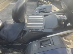
That is an old Phil's Farkels luggage rack and backrest (I have one also). Not sure if he makes that design anymore. You might want to contact him and see if he still makes it.I saw this set up at the national at eureka springs this year. Have a couple more pics of it. Dont know whose bike it was but im thinking if doing something similar for myself..
Mark