• Can't post after logging to the forum for the first time... Try Again - If you can't post in the forum, sign out of both the membership site and the forum and log in again. Make sure your COG membership is active and your browser allow cookies. If you still can't post, contact the COG IT guy at IT@Concours.org.
  • IF YOU GET 404 ERROR: This may be due to using a link in a post from prior to the web migration. Content was brought over from the old forum as is, but the links may be in error. If the link contains "cog-online.org" it is an old link and will not work.

Cam Chain Link Skip

wantabeach

Member
Member
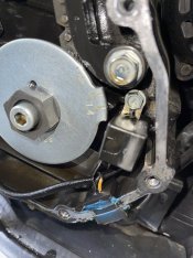
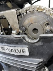
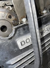
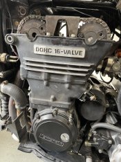
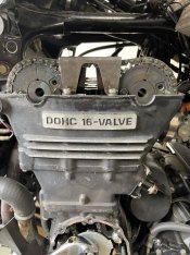
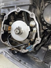
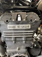
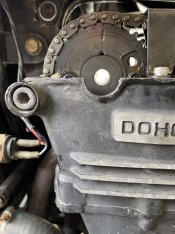
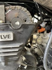
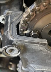
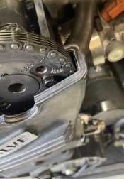
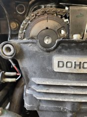
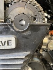
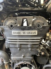
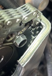
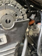
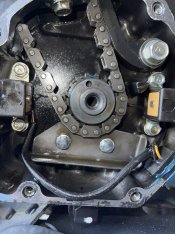
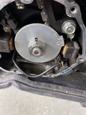
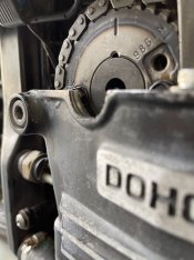
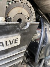
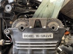
Well, I really did it this time. Got tired or hearing the cam chain rattle and purchased the APE manual adjuster. After reading so much about not overtightening the adjuster, I under tightened by a lot. When I hit the starter button, I heard it rattling and a sound like it was skipping so I stopped. I aligned the 1.4 T Mark to the index mark at the crank and pulled the valve cover off to find the cam sprockets appear to be 180 degrees off.

Scenario 1 - maybe the chain did not skip
I find it odd that I could have skipped it perfectly 180 degrees. Might I just need to rotate the 1.4 mark 180 degrees and see where I stand? My Clymer manual does not discuss it specifically but I see that in order the check the alignment after a cam installation, it says to rotate the crank two full turns.

Scenario 2 - chain skipped on the lower timing sprocket

It seems plausible that the chain could skip on the lower timing gear but not on the cam gears due to the upper cam chain guide. If that is the case, what is the fix?

Scenario 3 - chain skipped on the cam gear sprockets

Will this procedure work?
* Loosen valve adjustments from rocker
* Remove upper cam chain guide
* Remove cam chain tensioner
* Pick chain up enough to rotate cam into alignment?

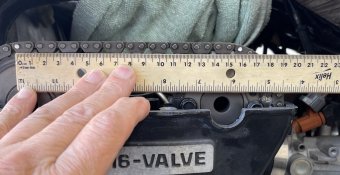
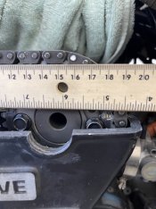
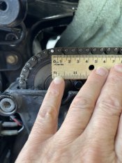
See attached pictures.

Paul
 

Attachments

  • IMG_2391.JPG
    IMG_2391.JPG
    149.9 KB · Views: 16
  • IMG_2393.JPG
    IMG_2393.JPG
    150.4 KB · Views: 15
  • IMG_2395.JPG
    IMG_2395.JPG
    140.6 KB · Views: 16
  • IMG_2397.JPG
    IMG_2397.JPG
    199 KB · Views: 15
Last edited:
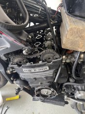
Update:

Well I took a chance and rotated the crank one full turn. The cam sprocket alignment marks get pretty close but there is a problem:

1) as you can see from the photo, in order for the cam sprocket marks to line up with the head, I needed to advance the T-Mark a little too far.

2) worse, I believe there is 38 teeth between the EX and IN marks. As you can see from the picture, the chain is riding high on the intake cam sprocket. So I guess this means I'm working with Scenario 3 (worst case).

Not sure how tolerant these timing chains are to this kind of stretching which could make matters worse. Should I go ahead a take the cam chain guide off to relieve the pressure?

Thoughts?

Paul
 

Attachments

  • IMG_2400.JPG
    IMG_2400.JPG
    188.2 KB · Views: 18
  • IMG_2404.JPG
    IMG_2404.JPG
    182.2 KB · Views: 18
Last edited:
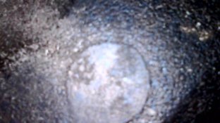
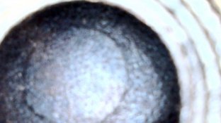
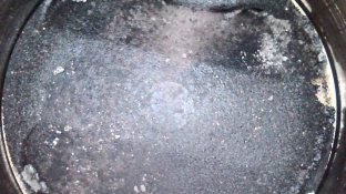
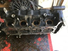
Update...here are some pictures of the top of the pistons.... Are pistons supposed to have a round circle in the middle or would that be a valve mark? Seems like a valve would hit at a slight angle and not leave a full circle but I could be wrong.
 

Attachments

  • IMG_2411.JPG
    IMG_2411.JPG
    80.2 KB · Views: 11
  • IMG_2412.JPG
    IMG_2412.JPG
    62.8 KB · Views: 11
  • IMG_2413.JPG
    IMG_2413.JPG
    135.3 KB · Views: 11
  • IMG_2414.JPG
    IMG_2414.JPG
    61.6 KB · Views: 11
It looks to me like your intake cam is late. Remove the guide between the cams and remove the tensioner. Rotate the intake cam NOT THE CRANK to bring the mark up which will bunch up the chain between the cams. Now try to walk the chain back around the intake sprocket. If it won’t go, you may have unbolt the intake cam caps to lift the cam and get the chain back where it belongs.
 
It looks to me like your intake cam is late. Remove the guide between the cams and remove the tensioner. Rotate the intake cam NOT THE CRANK to bring the mark up which will bunch up the chain between the cams. Now try to walk the chain back around the intake sprocket. If it won’t go, you may have unbolt the intake cam caps to lift the cam and get the chain back where it belongs.
Thanks Steve....I will try that and let you know.

Does that look like "love taps" from valves on top of those pistons?

Paul
 
Wantabeach, I agree that the intake cam seems late.
My guess is advancing 1 tooth on the Intake Cam may be all you need.

Question; Was the cam chain tight when you took the last photo's?

If it was loose it's possible that the cams may have rotated a bit because of the cam lobes / valve springs force.
That force may be causing a bit of extra cam rotation.
Additionally tightening the tensioner will remove the slack at the cam chain.
Removing that slack may possibly improve the appearance of the crank location.

Bottom line; Lets be sure where everything is currently.

"If the cam chain was not tight" for the photo's you posted, snug the chain and repeat the photo's.

Ride safe, Ted
I believe it was tight Ted. As you can see from the picture, the tensioner is in there (albeit looks like bolt, rod and spring removed). I will verify.

I took the upper chain guide off and counted 36 sprocket teeth from the EX mark to the IN mark, including the teeth at the marks. Am I counting this right? My Clymers manual says the count should be 35.

Ever heard of anyone successfully moving the chain over a tooth without taking cams off? I tried what Steve suggested above, but there just is not enough room without forcing it. Of course, I'm thinking about how I might force it. Obviously, can be done because it did jump under force.

Paul
 
It looks to me like your intake cam is late. Remove the guide between the cams and remove the tensioner. Rotate the intake cam NOT THE CRANK to bring the mark up which will bunch up the chain between the cams. Now try to walk the chain back around the intake sprocket. If it won’t go, you may have unbolt the intake cam caps to lift the cam and get the chain back where it belongs.
Thanks Steve, I tried to get that link by in intake sprocket tooth but no luck so far. I may try forcing it. Obviously, it can be forced through but may damage something. Have you been able to reindex a sprocket like this without pulling the cam?

Thanks
Paul
 
Clymer manual makes it seem like it’s no big deal. Just pick up the timing chain and index it to the marks while the cam lay in the journals.

What am I missing?

Better go to bed…..two late nights never produces anything good.

Thanks
Paul
 

Attachments

  • IMG_2416.jpeg
    IMG_2416.jpeg
    174.9 KB · Views: 4
Removing the cam caps isn't hard. Replace them in their proper positions (they're numbered), pointed correctly with the indicator arrows and torqued to specs in the specified sequence.

Removing that upper cam chain guard will help too. Use a shop magnet to keep from dropping one of the inside shorter bolts down into the cam chain cavity.

1725106235129.png


The valves are at an angle and wouldn't leave round witness marks like your piston pics show.

IMG_8164.JPG
 
Removing the cam caps isn't hard. Replace them in their proper positions (they're numbered), pointed correctly with the indicator arrows and torqued to specs in the specified sequence.

Removing that upper cam chain guard will help too. Use a shop magnet to keep from dropping one of the inside shorter bolts down into the cam chain cavity.

The valves are at an angle and wouldn't leave round witness marks like your piston pics show.
I may need to take cam(s) off to index but I'm going to try Steve's method again today.

That said, I also read that one needs plastigage (some kind of spacer) in the cam journal for the install to make sure there is room for oil? If so, what size, etc?
 

Attachments

  • IMG_2425.JPG
    IMG_2425.JPG
    166.2 KB · Views: 3
Do as Steve advised you in post #8.
His instructions are how I (faintly) remember doing it.

Ride safe, Ted
I am going to try to move the link without removing the cam again today. Its very close and it seems with the right level of pressure one might be able move the chain over the tooth and by the wall. There is actually a fraction more space on the exhaust side.
 

Attachments

  • IMG_2428.jpg
    IMG_2428.jpg
    141.4 KB · Views: 5
  • IMG_2430.jpg
    IMG_2430.jpg
    121.2 KB · Views: 5
Wantabeach, I agree that the intake cam seems late.
My guess is advancing 1 tooth on the Intake Cam may be all you need.

Question; Was the cam chain tight when you took the last photo's?

If it was loose it's possible that the cams may have rotated a bit because of the cam lobes / valve springs force.
That force may be causing a bit of extra cam rotation.
Additionally tightening the tensioner will remove the slack at the cam chain.
Removing that slack may possibly improve the appearance of the crank location.

Bottom line; Lets be sure where everything is currently.

"If the cam chain was not tight" for the photo's you posted, snug the chain and repeat the photo's.

Ride safe, Ted
Ok, I re-assembled cam chain tensioner and upper chain guide and rotated two full turns (counter clockwise) to return it to 1.4 TDC. Same result, EX even and IN low. See new pictures.
 

Attachments

  • IMG_2423.JPG
    IMG_2423.JPG
    182.8 KB · Views: 12
  • IMG_2422.JPG
    IMG_2422.JPG
    141.9 KB · Views: 12
  • IMG_2420.JPG
    IMG_2420.JPG
    188.4 KB · Views: 12
Last edited:
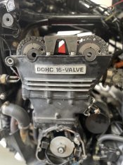
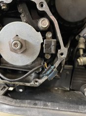
I don’t think it possible to index the cams without removing them or potentially breaking something. Just not enough room to get the link pass the teeth and cylinder wall. No obvious way to force it through either. Obviously, in my case it did get squeeze through as noted in my original post but I think it’s time to get the professionals involved and do it right.

Changed the name of the post so maybe someone else could find it and benefit.
 

Attachments

  • IMG_2437.jpeg
    IMG_2437.jpeg
    115.6 KB · Views: 6
  • IMG_2436.jpeg
    IMG_2436.jpeg
    131.9 KB · Views: 6
  • IMG_2431.jpeg
    IMG_2431.jpeg
    183.2 KB · Views: 6
As you don't want to do the caps, I'm wondering; Would it be possible to remove the 2 bolts from the exhaust Intake sprocket?
If so you might be able to move the sprocket to give yourself a tiny bit more clearance.

But, use extreme care not to lose bolts or alter the timing on the other cam while doing so.

If that is impossible, you'll have to take the caps off of loosen the bolts on the Intake cam caps as Steve sed in post #8.

Ride safe, Ted
 
Last edited:
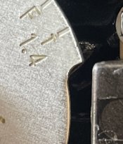
I don’t think it possible to index the cams without removing them or potentially breaking something. Just not enough room to get the link pass the teeth and cylinder wall. No obvious way to force it through either. Obviously, in my case it did get squeeze through as noted in my original post but I think it’s time to get the professionals involved and do it right.

Changed the name of the post so maybe someone else could find it and benefit.
Stop aggravating yourself, and do as Steve said in post #8. He is THE MAN, when it comes to everything c10. Why prolong the inevitable and possibly screw something up? In the words of Nike, just do it!!
 
Stop aggravating yourself, and do as Steve said in post #8. He is THE MAN, when it comes to everything c10. Why prolong the inevitable and possibly screw something up? In the words of Nike, just do it!!
You’re right about me aggravated. Steve is the man and I’m following his instructions. Tried to walk the chain back but it won’t go through the passage. So solution number two is to take the cam off and walk the chain back that way and reinstall. I’m just not comfortable doing that on my own so I’m going to get some help.

Paul.
 
Would it be possible to remove the 2 bolts from the exhaust sprocket?
If so you might be able to move the sprocket to give yourself a tiny bit more clearance.

But, use extreme care not to lose bolts or alter the timing on the other cam while doing so.

If that is impossible, you'll have to take the caps off of the Intake cam.
As Steve sed in post #8.
Wow this could be an easier solution if I can get the bolts and sprocket off without dropping them. Virtually no risk in getting the other side out of time since the chain cannot move down and there are 35 teeth between the marks on top. I assume you meant to say intake cam sprocket since that is the one I’m trying to re-index / move? I will give this some thought for sure and report back.

I missed this post yesterday so thank you!

Paul
 
Yupp, I meant to say intake.
What brought it to mind is; Steve used to sale a special exhaust sprocket.
As I recall, you didn't have to remove the cams (to install it).

I highly suggest special care if you do this.
Use a tie wrap to hold the chain in place on the exhaust sprocket, (use a sharpie to) mark the cam/sprocket alignment before you remove the intake sprocket, and also mark the chain and sprocket tooth at you want to use for reference, put rags below the bolts as you remove them.

When you're done, check "everything" twice!

Steve, please reply if I'm in-correct??

Ride safe, Ted
 
Last edited:
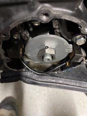
Yupp, I meant to say intake.
What brought it to mind is; Steve used to sale a special exhaust sprocket.
As I recall, you didn't have to remove the cams (to install it).

I highly suggest special care as you do this.
Use a tie wrap to hold the chain in place on the exhaust sprocket, (use a sharpie to) mark the cam/sprocket alignment before you remove the intake sprocket, and also mark the chain and sprocket tooth at you want to use for reference, put rags below the bolts as you remove them.

When you're done, check "everything" twice!

Steve, please reply if I'm in-correct??

Ride safe, Ted
I’m hoping to remove one bolt and maybe just loosen the other to roll the sprocket up a little. That way I can attached to the right link / tooth and then roll it back down. I will use ties on the exhaust sprocket to keep things solid. Hope to get back to it by Tuesday and report back.
 
The sprocket is located on a shoulder on the cam, so you would have to remove both bolts.

Looening the cam caps ( I never said to remove them) is imo your best bet. The spring tension will lift the cam up and give you more clearance. Work from the center cap out, back off each bolt 2 turns and then move outwards to the other caps doing the same. If the cam doesn’t lift on its own tap the caps it will pop up. Repeat if necessary. After you get the timing right, walk the cam back down by tightening each bolt 1turn per cap, again start in the middle and work out.

I can explain how to remove the sprocket, but that will be worse on you, as you then have to get the cam in time with the sprocket, and can only access 1 sprocket bolt at a time, having to rotate the whole assembly to access the other bolt.

Finally, don't even attempt to rotate the assembly unless the tensioner is in and the chain slack is out.

Steve
Wow....your right.......this is helpful.

I had planned to work one cam sprocket bolt at a time for sure; specially since both need loctite (can't just loosen one and retorque).

I definitely see the merit in your plan and would like to try it. Just have a couple questions:

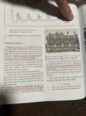
1) Do I need to concern myself with the purpose of the Plastigage noted in the manual in Camshaft Oil Clearance section?

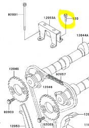
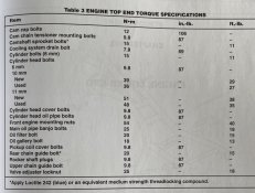
2) Also, the outside bolts of the upper cam chain guide are longer and appear to go down into the block. They were much harder to get out but I followed your video and taped the hex socket down pretty hard and got then out (started to strip a little so may replace). I'm not sure if I should follow the torque guidance for upper chain guide (87 in-lb) for these or cylinder bolts or cylinder head bolts as noted in the manual (see picture attached).

What a journey so many thanks,

Paul
 

Attachments

  • IMG_2441.jpg
    IMG_2441.jpg
    164.4 KB · Views: 0
Wow....your right.......this is helpful.

I had planned to work one cam sprocket bolt at a time for sure; specially since both need loctite (can't just loosen one and retorque).

I definitely see the merit in your plan and would like to try it. Just have a couple questions:

1) Do I need to concern myself with the purpose of the Plastigage noted in the manual in Camshaft Oil Clearance section?

2) Also, the outside bolts of the upper cam chain guide are longer and appear to go down into the block. They were much harder to get out but I followed your video and taped the hex socket down pretty hard and got then out (started to strip a little so may replace). I'm not sure if I should follow the torque guidance for upper chain guide (87 in-lb) for these or cylinder bolts or cylinder head bolts as noted in the manual (see picture attached).

What a journey so many thanks,

Paul
If I don’t mention something specifically they it’s probably not an issue. I’m just wondering how you or anyone could get plastiguage between the cam and the cap that you’re not trying to remove. The bolts were more difficult to remove becuase of corrosion from disimilar metals which increases breakaway torque. Plus the longer bolts will twist more than the short ones which increases the sense of force needed.


ETA the long bolt that hold the chain guide are chain guide bolts not head bolts.

Steve
 
Last edited:
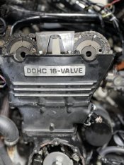
Wantabeach I saw a post from you that I cannot see anymore?
You had photo's and asked if it looked right.
I assume that the post will reappear eventually.

During the short time I could see the photo's,,, something didn't look right.
But I didn't have e'nuff time to really look at the images.

Did you adjust the tensioner and rotate the engine several times before taking the photo?
The reason I ask is the chain appears to have slack {between the sprockets} and the sprocket bolts were level. (not slightly angled).

Ride safe, Ted
 
Last edited:
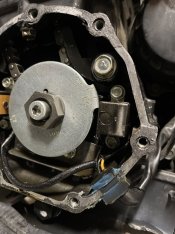
Please don’t be frustrated with me everyone - I’m at my limits. I appreciate everyone’s helps more than you can know!

I was able to lift the intake cam (by loosening the cam cap bolts all the way) and advanced the intake cam only to realize both marks were too high off the deck when the T-Mark at the crank was indexed so I reversed it.

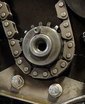
I was counting sprocket teeth between the marks and should have been counting cam chain pins which made me think the problem was at the cam gears. There are 35 pins between the marks now and they are perfectly on top of the deck of the heads when the T-Mark on the rotor is past the timing mark index.

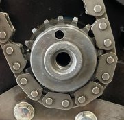
I guess that means that it jump a tooth at the crank gear? The Clymer manual talks about removing the timing rotor and gear at the crankcase in the context of the head being removed so that was not helpful for me.

Maybe I can figure out a way to advance both cam’s and affect the same thing?

Is there any easy way to get the crank gear off and re index that way?

Or maybe take upper guide, tensioner and rotor off then skip it back?

Pictures below are of the current state with marks level with the deck.

Thanks everyone
Paul.
 

Attachments

  • IMG_2452.jpeg
    IMG_2452.jpeg
    133.6 KB · Views: 18
  • IMG_2455.jpeg
    IMG_2455.jpeg
    104.5 KB · Views: 18
Last edited:
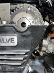
Please don’t be frustrated with me everyone - I’m at my limits. I appreciate everyone’s helps more than you can know!

I was able to lift the intake cam (by loosening the cam cap bolts all the way) and advanced the intake cam only to realize both marks were too high off the deck when the T-Mark at the crank was indexed so I reversed it.

I was counting sprocket teeth between the marks and should have been counting cam chain pins which made me think the problem was at the cam gears. There are 35 pins between the marks now and they are perfectly on top of the deck of the heads when the T-Mark on the rotor is past the timing mark index.

I guess that means that it jump a tooth at the crank gear? The Clymer manual talks about removing the timing rotor and gear at the crankcase in the context of the head being removed so that was not helpful for me.

Maybe I can figure out a way to advance both cam’s and affect the same thing?

Is there any easy way to get the crank gear off and re index that way?

Or maybe take upper guide, tensioner and rotor off then skip it back?

Pictures below are of the current state with marks level with the deck.

Thanks everyone
Paul.
Rotate the crank 2 revolutions and STOP On the T mark. Look at the cams. They will only be slightly off. Imagine moving each cam 1 tooth. I think it will be way to much. I think what you’re seeing is everything in proper time, and maybe a bit of cam chain stretch.
 
Rotate the crank 2 revolutions and STOP On the T mark. Look at the cams. They will only be slightly off. Imagine moving each cam 1 tooth. I think it will be way to much. I think what you’re seeing is everything in proper time, and maybe a bit of cam chain stretch.
I think you’re right. Camera pictures make it hard to see but the EX mark is probably 1mm high and IN mark 1 mm low when the T Mark is index perfectly. Separation at the top of a cam tooth is like 9mm. I know that’s probably not exactly comparable but proves the point. I suppose chain slack can account for the 1 mm index issue. I’ll put it back together and hope for the best. I worked that cam down real slow (like 1/4 turns) from the inside out in accordance with the patterned noted in the manual.

If all works out, at least I got a good valve adjustment out of it and some peace of mind of course.

Still thinking about putting that manual cam chain tensioner in there! At least I’ll be able to test the slack better this time. I had an 06 C10 before and it was dead quite after warm up. This 92 chain slaps around pretty hard when cold and never really goes away until it’s hot on a summer’s day and then you still hear it a little.

Do you run manual cam chain tensioners?

Paul.
 
Last edited:
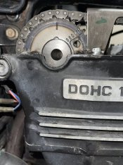
I agree with Steve. You might have the cam timing right.

{Finish tightening the cam caps} then stop, rotate the crank a couple of rotations, and stop at the T.
Then post photo's of the timing plate and the cams...

I think what you're seeing is Timing Chain stretch.
But there is 1 other possibility.

ie; The timing plate may have rotated.
If you {or a prior owner) ever turned the engine using "only" the big nut, "it" may have rotated slightly.

NOTE: When I rotate the engine, I "always" use the big nut on the timing plate "and" an Allen wrench in the socket head bolt at the end of the crank.
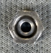
Reason being; That big nut is not a nut.
It's the timing plate mount and is kept from rotating by "only" a small shear pin.

Ride safe, Ted

PS: I've had 5 C-10's and never used a manual tensioner.
The fact that you're getting a lot of noise may be an indication of timing chain stretch/wear.
Did you measure the stretch while you were counting the links? (page 4-13 of the manual)
 
Last edited:
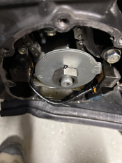
I agree with Steve. You might have the cam timing right.

{Finish tightening the cam caps} then stop, rotate the crank a couple of rotations, and stop at the T.
Then post photo's of the timing plate and the cams...

I think what you're seeing is Timing Chain stretch.
But there is 1 other possibility.

ie; The timing plate may have rotated.
If you {or a prior owner) ever turned the engine using "only" the big nut, "it" may have rotated slightly.

NOTE: When I rotate the engine, I "always" use the big nut on the timing plate "and" an Allen wrench in the socket head bolt at the end of the crank.
Reason being; That big nut is not a nut.
It's the timing plate mount and is kept from rotating by "only" a small shear pin.

Ride safe, Ted

PS: I've had 5 C-10's and never used a manual tensioner.
The fact that you're getting a lot of noise may be an indication of timing chain stretch/wear.
Did you measure the stretch while you were counting the links? (page 4-13 of the manual)
I did not get a chance to count the pins but I may before it’s all over.

The crank has been rolled over a number of times now for the valve adjustments so the chain should have redistributed well. I use the hex and nut (which is not a nut) and no plugs turning counter clockwise. I little more than half the pressure I apply to the hex because that nut looks weak and I’m always looking at that roll pin in fear of shredding it. But you do see in one of the pictures that the nut is pushed into the pin a bit.

As you can see, the T Mark is on the index and the EX mark is a little high and IN mark a little low off the deck.

Paul.
 

Attachments

  • IMG_2471.jpeg
    IMG_2471.jpeg
    102.4 KB · Views: 21
  • IMG_2476.jpeg
    IMG_2476.jpeg
    138.8 KB · Views: 23
  • IMG_2473.jpeg
    IMG_2473.jpeg
    149.4 KB · Views: 22
  • IMG_2477.jpeg
    IMG_2477.jpeg
    129.9 KB · Views: 21
  • IMG_2478.jpeg
    IMG_2478.jpeg
    174.8 KB · Views: 18
Last edited:
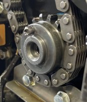
It still looks wrong to me. When everything is right the cam sprockets will look like mirror images of each other.

The whole procedure depends on the crank location, not the cam locations. By keying in on the cam locations but allowing the crank to be out of time you tricked yourself visually, then it’s downhill from there.
 
Last edited:
It still looks wrong to me. When everything is right the cam sprockets will look like mirror images of each other.

The whole procedure depends on the crank location, not the cam locations. By keying in on the cam locations but allowing the crank to be out of time you tricked yourself visually, then it’s downhill from there.

After all the back and forth about moving chain links, and me discovering how to count the pins between the marks, everything is back to where it started. Both of the following perspectives were taken under the same conditions:
1) When the cam marks are flat on the deck, the T-Mark is early (past the index mark); see post #32.

2) When the T-Mark is index, the cam marks are late (EX above the deck and IN below the deck); see post #36.

Possible causes noted include:

1) Stretch in timing chain.

2) Timing plate may have moved. If that is the case, what is the affect? Is it just visual or does that throw off the timing advance?

Thanks everyone!
Paul
If the timing plate has moved everything is hosed. That’s the technical term. Btw that’s the exact reason I asked how you were turning the crank.

If it was me, I’d pull the timing plate off and be sure the roll pin is intact and the timing plate is properly located. If it is, great . If not it’s a full stop and repair before moving forward. Remember, cam timing depends first on proper crank timing. If the crank is out everything is out of time.

I've read a few war stories on taking this off (guy who slicked his hand open). Any special tricks? Do I just hold the nut with a wrench and turn the hex bolt counterclockwise? Or maybe it is better to just put the back wheel on the ground and put it into gear to lock the crankshaft in place (this seems safer)? My manual gives not details on this procedure, so any help is greatly appreciated!

The manual refers to aligning a dowel on the end of the crank; is just another word for the "roll pin" ?

Thanks
Paul
 
Paul in your second photo the T appears to be lined up correctly and the cams both appear late.
(Assuming the Cam Photo's were done with the "T" aligned)
This indicates (as you/Steve said) you have either a stretched timing chain, or the timing plate has moved.

In your first photo {below} the notch in the big nut and the notch in the plate are not aligned.
Additionally the photo may show that the pin is partially sheared.

Do as Steve sez; Pull the timing plate off and be sure the roll pin is intact, and the timing plate is properly located.

EZ to do.
Hold the big nut with a wrench and unscrew "the socket head cap screw".
Do NOT turn the big nut!!
(Putting the bike in gear with the wheel on ground might also be good to do, but not needed).

After the cap screw is removed, the timing plate will come off so that you can inspect it.
{You can also inspect the crank sprocket with it removed}.

Ride safe, Ted
 

Attachments

  • 1725478793860.png
    1725478793860.png
    1.1 MB · Views: 4
Last edited:
Thank you both so very much. Please forgive me for asking but out of the abundance of caution, I must ask: does the hex bolt loosen by rotating it counterclockwise?
 
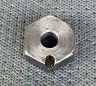
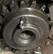
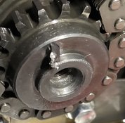
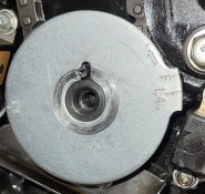
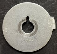
Ok....here is what I have: Looks like the nut, roll pin and timing plate have seen better days. Not sure how it could have happened, but I look forward to hearing from the experts. I'm curious what could cause the scaring around the timing plate hole and the back of the nut as it looks like that thing spun several times under a lot of stress. Don't see how the scaring could have occurred during the situation I described in my first post but love to hear what you think. I got the biked used with 30k miles so maybe something occurred during previous ownership, and they just forced the timing plate and to get it close. I have adjusted valves once before and used the starter method to turn the crank after reading about it on the forum. I did turn the crank this go around with the hex and nut, plugs out, go slow, equal pressure, counterclockwise, so I'm confident it did not occur during my diagnostics.

Do you think there is enough damage to the nut, plate and pin to cause my timing issues?

Looks like I will need to replace all three.....? Hope that stuff is available.

Many thanks
Paul
 

Attachments

  • IMG_2487.jpg
    IMG_2487.jpg
    133.4 KB · Views: 19
  • IMG_2493.jpg
    IMG_2493.jpg
    244.1 KB · Views: 19
  • IMG_2497.jpg
    IMG_2497.jpg
    150.7 KB · Views: 19
  • IMG_2498.jpg
    IMG_2498.jpg
    167.5 KB · Views: 16
  • IMG_2500.jpg
    IMG_2500.jpg
    317 KB · Views: 16
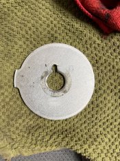
It looks like the nut spun over the rollpin , but did the ignition plate? That’s the issue. Was the plate located by the pin when you disassembled it? Can you take a pic of the backside of the plate?
 
It looks like the nut spun over the rollpin , but did the ignition plate? That’s the issue. Was the plate located by the pin when you disassembled it? Can you take a pic of the backside of the plate?
The plate notch was properly located around the pin when I disassemble it.
 
Last edited:
Yes...sorry I missed that one. Doesn't look too bad but there is some damage.
 

Attachments

  • IMG_2484.JPG
    IMG_2484.JPG
    266.6 KB · Views: 10
Last edited:
Doesn’t look spun. Put it all back together in time. You know everything you need to do.
Awesome…..but just so you see another perspective, here are a few more pictures of the roll pin damage. You can see that it’s bent over a little.

I’m a little concerned now that it might shear off in time. Is removing / replacing it an extensive process?
 

Attachments

  • IMG_2505.jpeg
    IMG_2505.jpeg
    205.6 KB · Views: 22
  • IMG_2504.jpeg
    IMG_2504.jpeg
    197.7 KB · Views: 22
Awesome…..but just so you see another perspective, here are a few more pictures of the roll pin damage. You can see that it’s bent over a little.

I’m a little concerned now that it might shear off in time. Is removing / replacing it an extensive process?

Oh boy....

You're getting into the weeds here. I'd recommend stopping while you're ahead and look up some videos on the entire process to R&R the cams. That will also help you with setting timing.

And to elaborate on Steve's comment; that pin damage is BAD. And the last thing you want is for that piece of fatigued metal to break off near your timing chain and cams. You should replace it.

Where are located? There may be a member near you that could help.

-Z
For $50 I can replace the timing plate, pin, nut and bolt if I can figure out how to do it. I cannot find anything in my Kawasaki or Clymer manual about replacing this roll pin (dowel). I got myself into this mess by just jumping in and trying to do something without thinking through it more and I'm trying to avoid that now. I don't know if that thing gets pressed in there by a machine shop or is just lightly seated. I don't want to mangle it trying to get it out, just to discover that one needs to remove the gear first (not within my skill set), in which case I would put it all back together as is and come back to it when I have more time. I just got a contract on my house, so I'm feeling the pressure to get this off my plate but I like to do things right.

The only thing I know to do is grab that pin with some heavy pliers and try to pull it out and then tap another one in lightly with a hammer. Does that sound about right?

Thank you,
Paul
Why not just try it? How do you think everyone else learned?
 
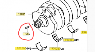
Listen, don't overthink it. Replace the roll pin (item 555 in the schematic) - it's clearly damaged. Also, that is not a removable gear - it's the end of the crankshaft. The only way that pin goes in or comes out is as you described. For peace of mind, you might as well replace the nut and the plate, the bolt should be fine. Once you get that done you can go back to getting the timing set correctly.

1725549281141.png

1725549334888.png
 
Listen, don't overthink it. Replace the roll pin (item 555 in the schematic) - it's clearly damaged. Also, that is not a removable gear - it's the end of the crankshaft. The only way that pin goes in or comes out is as you described. For peace of mind, you might as well replace the nut and the plate, the bolt should be fine. Once you get that done you can go back to getting the timing set correctly.

View attachment 39960

View attachment 39961

Thank you so much for this. I will order the parts and get it done. Since, the timing is fixed on this bike, does "setting the timing mean" making sure my cam marks and T-marks are aligned properly? I will hook up a timing light to verify timing in the end.

Many thanks
Paul
 
Dont order parts. Yours are serviceable. Just replace the roll pin.

I’m thinking this happened before you owned the bike, and I wouldn’t doubt the cam has been out of time all along. This is what happens when people “try to save money”. I know I’m the odd man on this , but I’ve see alot of “trying to save money” work. My takeaway is that there’s a reason there’s mechanics, carpenters , lawyers, and doctors. Sometimes it’s best to stay in your own lane, unless you want to try your hand at surgery with a circular saw.

ETA cam timing and ignition timing are 2 completely different things. Surgery with a circular saw.
 
Paul, I'm going to be the naysayer here and I have a reason.
I've heard of others that tried to get those pins out and were unsuccessful.

That pin (roll pin) is made of Spring Steel.
If you break it off while trying to pull it out, it's doubtful that you could get the remaining piece of the rollpin out of the crankshaft.
ie; Can't be drilled if you break it off flush with the surface.
If that happens, the crankshaft will probably have to be removed from the bike.


Going back; It's obvious that the pin was damaged by someone turning the engine with the big nut.
Turning that (Nut) crushed and deformed the pin.
{It's possible the deformation will make it possible to gently remove the pin, but it's also possible that you could break the pin while trying to get it out}.

Luckily the hole doesn't appear to be damaged, but unfortunately the pin is partially collapsed.
{Which means the timing plate wouldn't be exactly located}.

You can try to "gently" pull it out.
ie; Do not bend or crush it with vise grip pliers.
If it doesn't come out easily, you can do exactly what Steve said. (reassemble and give it a try)

It's your choice.

Ride safe, Ted

PS: If you choose to use it as is, you could possibly modify the plate to assure it stays in place.
 
Parts ordered. BTW everything was available except the pin from Partzilla but I was able to find it on eBay NOS. I feel like Forest Gump - I’ve come this far…..

You got this. You know what to do. So say "F it!" and take the plunge, brother.

Either you fix it and you get to bask, or you mess it all up to hell and you learn from it. 😎

-Z
 
While you're waiting for the parts can you place the plate on the crankshaft (orient it as precisely as you can) to check your current cam timing?

Ride safe, Ted
 
While you're waiting for the parts can you place the plate on the crankshaft (orient it as precisely as you can) to check your current cam timing?

Ride safe, Ted

See attached picture of the current state of affairs. The EX and IN cam marks are flat on the deck (not shown here). The timing plate wiggles back and forth a MM or so. You will recall from post #50 that the pin is deformed and pushed to the left and the plate is damage as seen in post #45 and #48. For this picture, I max out the clockwise position but as you can see, the T Mark is early (advance?). This picture is only slightly closer to the index mark that the one in post #32.

So I guess it will be difficult to predict where it might wind up after I install the new pin and timing plate but my guess is that the T Mark will be closer to the index mark primarily due to the bent pin.

Paul
 

Attachments

  • IMG_2512.jpg
    IMG_2512.jpg
    257.3 KB · Views: 12
Last edited:
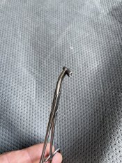
Well there must be a God. Surgery…..yes but not with a circular saw. Pin was pinched against the wall and would not come out after a few tugs. I took a chance with a punch and centered it and then it spun a little. These forceps came in handy. That’s a load off my back.
 

Attachments

  • IMG_2542.jpeg
    IMG_2542.jpeg
    186.7 KB · Views: 13
  • IMG_2541.jpeg
    IMG_2541.jpeg
    193.2 KB · Views: 14
See attached picture of the current state of affairs. The EX and IN cam marks are flat on the deck (not shown here). The timing plate wiggles back and forth a MM or so. You will recall from post #50 that the pin is deformed and pushed to the left and the plate is damage as seen in post #45 and #48. For this picture, I max out the clockwise position but as you can see, the T Mark is early (advance?). This picture is only slightly closer to the index mark that the one in post #32.

So I guess it will be difficult to predict where it might wind up after I install the new pin and timing plate but my guess is that the T Mark will be closer to the index mark primarily due to the bent pin.

Paul
Paul you're doing this backwards. It's very hard for us to help you if you do not do as we have said.
(See Steve's post #37)

Do not line up the Cams and see where the T mark is.
(doing it this way is wrong and the information is incorrect)

You must line up the T mark with the Index Mark and then check the Cam locations.
(doing it this way is the only way to know where you're timing actually is)

I understand that previously the pin was warped and not centered.
If the T had been aligned in that photo we would have known (approximately) where your timing was.
Unfortunately it wasn't.

While you're waiting for the parts; (& if you want to know where you're timing actually is) we can tell you if the timing is ok,,
if you do this;

Carefully align the plate with the hole, (using a temporary/removable pin of some type)
Rotate the crank by putting the bike in gear and rotate the engine (CCW). (using the back wheel)
Take photo's of the T mark vs the Index mark and photo's of the cams vs the top of the head at that time.

Ride safe, Ted

PS: I'm very happy that you were able to remove the roll pin.
You're most of the way to the solution.
The rest is EZ.
 
Last edited:
Well there must be a God. Surgery…..yes but not with a circular saw. Pin was pinched against the wall and would not come out after a few tugs. I took a chance with a punch and centered it and then it spun a little. These forceps came in handy. That’s a load off my back.
Sweet. All the other parts are serviceable if you clean them up with a file. If the plate is loose on the pin you can punch the plate to tighten the slot. Yes i know new parts are on order but you can easily revisit to install the new parts. At least you can move forward now.
 
Paul you're doing this backwards. It's very hard for us to help you if you do not do as we have said.
(See Steve's post #37)

Do not line up the Cams and see where the T mark is.
(doing it this way is wrong and the information is incorrect)

You must line up the T mark with the Index Mark and then check the Cam locations.
(doing it this way is the only way to know where you're timing actually is)

I understand that previously the pin was warped and not centered.
If the T had been aligned in that photo we would have known (approximately) where your timing was.
Unfortunately it wasn't.

While you're waiting for the parts; (& if you want to know where you're timing actually is) we can tell you if the timing is ok,,
if you do this;

Carefully align the plate with the hole, (using a temporary/removable pin of some type)
Rotate the crank by putting the bike in gear and rotate the engine (CCW). (using the back wheel)
Take photo's of the T mark vs the Index mark and photo's of the cams vs the top of the head at that time.

Ride safe, Ted

PS: I'm very happy that you were able to remove the roll pin.
You're most of the way to the solution.
The rest is EZ.
I have certainly followed your instructions as noted in post #36 and #38.

Seems like both viewpoints tell you if your in time as long as you don’t move the crank clockwise, and bring chain slack into the equation.

I will definitely follow proper procedure again when I get the new parts.

Thanks
Paul.
 
In 36 and 38 (and all other photo's) the Timing plate was not in the correct position.
(It had rotated a few degrees on the crankshaft and we do not know which way it had rotated).
Lining up the cams do not give us the information we need.
It is some information, but we need the photo's done with the crank/timing plate in the correct position.

Ride safe, Ted
 
Last edited:
Photo's on post #36 were posted before he got the pins between the sprockets correct.

Ride safe, Ted
 
Last edited:
Photo's on post #36 were posted before he got the pins between the sprockets correct.

Ride safe, Ted

I figured out how to count the pins in post #32. In post #32, I rotated the engine twice counter-clockwise and stop when the cam marks were even with the deck just to verify that my distance between the cam marks was working.

My reference in post #36: "I did not get a chance to count the pins but I may before it’s all over." related to your suggestion to measure the cam chain stretch. The pictures in post #36 were done in response to your request in post #35 "{Finish tightening the cam caps} then stop, rotate the crank a couple of rotations, and stop at the T. Then post photo's of the timing plate and the cams..."

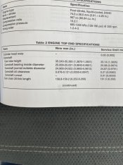
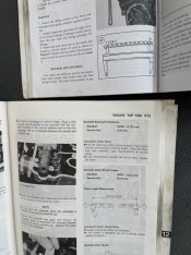
I measured the timing chain today. Now the manual says to remove the chain and stretch it out on a bench to measure it but I'm not going to do that right now. I just removed the upper chain guide, left in the tensioner in so chain was tight, and counted 21 pins (fingernail polish) and measured about 160mm which is within the service limit of 161.5. Angle of the pictures make it hard to see and the last pin is dipping down slightly but should be within the limit.

Chain not the problem.
 

Attachments

  • IMG_2584.jpg
    IMG_2584.jpg
    113.1 KB · Views: 4
  • IMG_2585.JPG
    IMG_2585.JPG
    119.2 KB · Views: 3
  • IMG_2586.JPG
    IMG_2586.JPG
    106.6 KB · Views: 4
  • IMG_2587.JPG
    IMG_2587.JPG
    139.7 KB · Views: 4
Last edited:
Real quick question that may have already been addressed;

Do you have a factory service manual? Not the Clymer, but the factroy manual?

-Z
 
Real quick question that may have already been addressed;

Do you have a factory service manual? Not the Clymer, but the factroy manual?

-Z
Clymer on top and Kawasaki on bottom. The factory manual is deceiving. It says 20 links but the graphic points to the pins. It definitely takes 21 pins to have 20 links. Clymer got it right.
 

Attachments

  • IMG_2603.jpeg
    IMG_2603.jpeg
    153.7 KB · Views: 9
Clymer on top and Kawasaki on bottom. The factory manual is deceiving. It says 20 links but the graphic points to the pins. It definitely takes 21 pins to have 20 links. Clymer got it right.
Well, it's 20 links total if you count both inside and outside links. But yes, that's 21 pins from end to end.
 
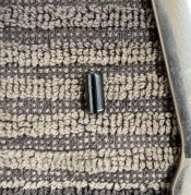
So got my parts in and started to install the roll pin but it really does not want to go. As you can see, the edge of the hole on the crank is sharp so it does not help the pin to collapse. If you look at the pin on one side you can see where my first attempt started to cut into it.

Should I squeeze the pin a bit? Should I use a little grease? Special tools?

Thanks
Paul
 

Attachments

  • IMG_2627.jpg
    IMG_2627.jpg
    155.8 KB · Views: 5
  • IMG_2631.jpg
    IMG_2631.jpg
    265.8 KB · Views: 5
As exactly as possible, measure the pin and hole diameters. (??? / ???)
Needs to be pretty close to the same diameter.

Here is a chart to help figure the approx. interference you want.
Looks like the Hole should be approx. .005" smaller than the "nominal" pin size or .010" smaller than the measured pin size.

You could gently polish a "slight" entry chamfer on the end of the pin, and the entry to the hole.
Then freeze the pin to get it smaller.
Once the edges are smoothed and the pin frozen you should be able to tap in it.

If that fails, you could possibly build a tool to partially push the pin in.

ie; Install the socket head cap screw and use a pry bar {between the pin and the cap screw} to start pushing the pin in.

To make the tool you could grind a larger slot in the end of a pry bar.
(sized to fit under the head of the socket head cap screw)

Harbor Freight has inexpensive pry bars that could be modified.

Ride safe, Ted
 
Last edited:
So got my parts in and started to install the roll pin but it really does not want to go. As you can see, the edge of the hole on the crank is sharp so it does not help the pin to collapse. If you look at the pin on one side you can see where my first attempt started to cut into it.

Should I squeeze the pin a bit? Should I use a little grease? Special tools?

Thanks
Paul
It's supposed to be tight, so it can't work itself loose and fall out. Usually roll pins have one end that has a more distinct taper to the end of the roll pin to make it easier to drive it in. Grab some needle nose pliers to try and squeeze the roll pin as u tap it in...a little oil, not grease, wouldn't hurt.
 
Ok....thanks everyone. Got the pin in there after squeezing the end in a little in a vice (probably not the best idea but it worked), buffing it a little with a fine file and applying a little grease. It was the right size as both the old and the new measured 4mm on the caliper; the new one being ever so slightly bigger.

Looking good so far but how about the alignment?
 

Attachments

  • IMG_2632.JPG
    IMG_2632.JPG
    131.2 KB · Views: 5
Well the alignment is not perfect but its real close. Hard to be exact so I gave you a few angles. If the camera is to high, it makes it look like the cam marks have more clearance between the deck and if to low, just the opposite. To my eye, the marks follow the pattern noted by Ted and Steve which note that the cams appear slightly late; probably due to chain slack.

Yes...the recommended procedure was followed: two full counterclockwise rotations of the crank with the T Mark landing on the index as seen in the pictures.

What do you think? Button her up and put fire in the hole?

Paul
 

Attachments

  • IMG_2654.JPG
    IMG_2654.JPG
    112.2 KB · Views: 7
  • IMG_2652.JPG
    IMG_2652.JPG
    126.2 KB · Views: 9
  • IMG_2640.JPG
    IMG_2640.JPG
    188 KB · Views: 9
  • IMG_2633.JPG
    IMG_2633.JPG
    172.7 KB · Views: 9
Last edited:
Top