Before I lose it ... almost threw it in trash with other stuff... here is the simple to follow foolproof outline I followed to hookup my Rostra CC to my 2012 C14. Note, pre-2010, might be slightly different. Also, on the VSS signal up in the front left boot, I got my wire "under" the connector - word is it changes color above the connector.
It is possible to put both relays up front, there is room for them if you make good multiple connections to the accessory plus and minus leads, and it makes wiring simpler.
Some of the wires coming from the Actuator are very short and hidden under the tape wrap closest to the Actuator.
This is correct for the switch with an engage light (...92 I think)
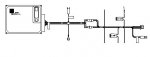
Front Boot
(+) (Female) accessory lead to : 1) Rostra Actuator brown and red wires, 2) Switch (Engage light version) white and gray wires, 3) #1 (front) relay pin 30 and 86
(-) (Male) accessory lead to: 1) Rostra Actuator black, 2) Switch black and blue wires
Actuator light green wire to black wire with white dots (below connector) (do not hook up until after diagnostics are done)
Rear Boot
Actuator blue wire to #2 (rear) relay pin 86 and 87
(-) (Male) accessory lead to #2 relay pin 85 and 87A
VSS Sending Unit (left side of bike, on top of crankcase cover)
This is the sending unit held on the left side crankcase cover with a single bolt. Disconnect it at the connector before making this connection.
Actuator gray wire to sending unit pink wire
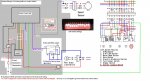
Viewed from the relays
Relay 1:
Pin 30, 86 to front boot (+)(female)
Pin 85 to Actuator orange wire
Pin 87 to Switch pink wire
Relay 2:
Pin 30 to Actuator violet wire
Pin 85, 87A to rear boot (-)(male)
Pin 86, 87 to Actuator blue wire
It is possible to put both relays up front, there is room for them if you make good multiple connections to the accessory plus and minus leads, and it makes wiring simpler.
Some of the wires coming from the Actuator are very short and hidden under the tape wrap closest to the Actuator.
This is correct for the switch with an engage light (...92 I think)
Front Boot
(+) (Female) accessory lead to : 1) Rostra Actuator brown and red wires, 2) Switch (Engage light version) white and gray wires, 3) #1 (front) relay pin 30 and 86
(-) (Male) accessory lead to: 1) Rostra Actuator black, 2) Switch black and blue wires
Actuator light green wire to black wire with white dots (below connector) (do not hook up until after diagnostics are done)
Rear Boot
Actuator blue wire to #2 (rear) relay pin 86 and 87
(-) (Male) accessory lead to #2 relay pin 85 and 87A
VSS Sending Unit (left side of bike, on top of crankcase cover)
This is the sending unit held on the left side crankcase cover with a single bolt. Disconnect it at the connector before making this connection.
Actuator gray wire to sending unit pink wire
Viewed from the relays
Relay 1:
Pin 30, 86 to front boot (+)(female)
Pin 85 to Actuator orange wire
Pin 87 to Switch pink wire
Relay 2:
Pin 30 to Actuator violet wire
Pin 85, 87A to rear boot (-)(male)
Pin 86, 87 to Actuator blue wire
") , your bike (like Brian's as originally wired) will not disengage the CC if the brake/tail light circuit fuse is blown when the brakes are applied, in fact in that situation the CC will open the throttle even wider attempting to maintain speed and fight the brakes until you pull in the clutch lever. An unlikely event but still possible and if it happens at just the wrong time.....well next time you have the top covers off, just move the wires. :great:
, your bike (like Brian's as originally wired) will not disengage the CC if the brake/tail light circuit fuse is blown when the brakes are applied, in fact in that situation the CC will open the throttle even wider attempting to maintain speed and fight the brakes until you pull in the clutch lever. An unlikely event but still possible and if it happens at just the wrong time.....well next time you have the top covers off, just move the wires. :great: